Eaton 9155 8-15 kVA.pdf - 第10页
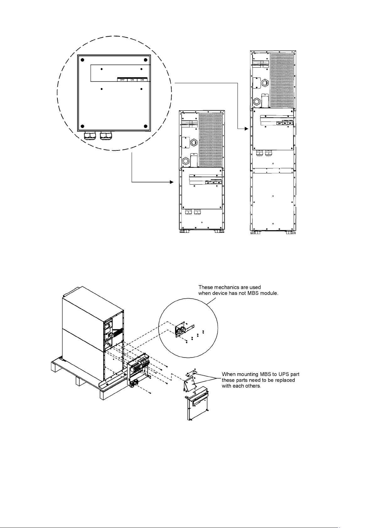
UPS 8 – 15 kV A, 230V 50/60 Hz output User ’ s Guide 1 022403 Revision D 1 0 Figure 7. The maintenance bypass switch (MBS) when installed in the backside. Figure 8. 9155 MBS assembly
UPS 8 – 15 kVA, 230V 50/60 Hz output
User’s Guide
1022403
Revision D
9
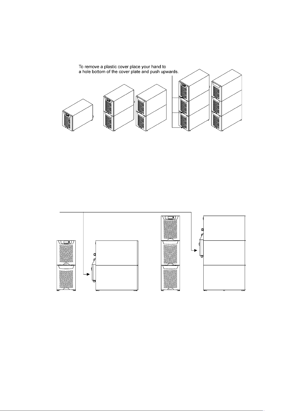
4. Cabinet installation
The required distance for UPS units next to each other is ten millimetres. The same applies to
the optional battery cabinets that should be installed next to the UPS cabinet.
Figure 5. UPS and external battery cabinets.
The UPS family has several alternative battery cabinets and configurations depending on the
selected back-up time and quality of batteries.
Maintenance bypass switch
The maintenance bypass switch (MBS) shall be mounted in back of the UPS battery
compartment. It can be ordered factory installed.
Figure 6. Instructions for locating the mechanical bypass switch.
Please fix the switch MBS to the wall (din rail) or to the back of the UPS as shown below.
UPS 8 – 15 kVA, 230V 50/60 Hz output
User’s Guide
1022403
Revision D
10
Figure 7. The maintenance bypass switch (MBS) when installed in the backside.
Figure 8. 9155 MBS assembly
UPS 8 – 15 kVA, 230V 50/60 Hz output
User’s Guide
1022403
Revision D
11
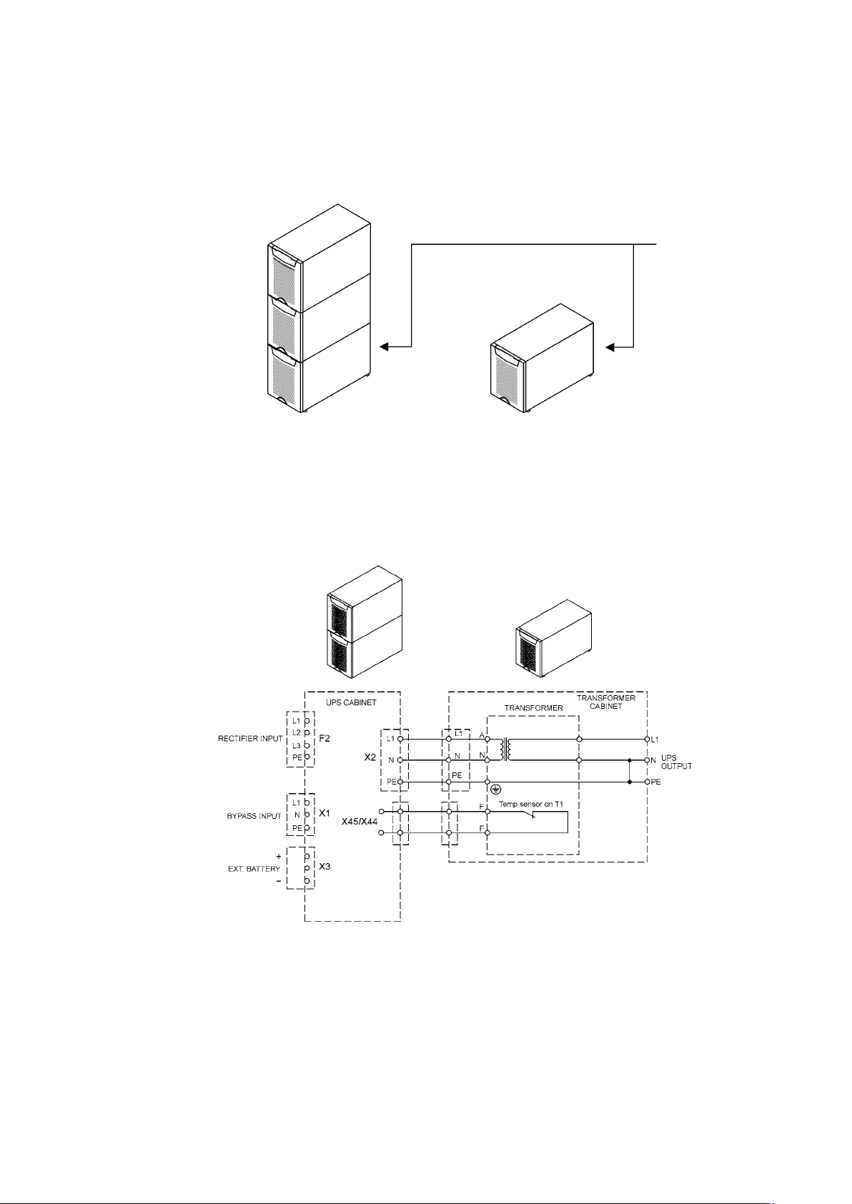
Transformer option
The galvanic isolation transformer can be ordered as factory installed. The transformer is an
integral part of the UPS unit. Alternatively, the isolation transformer can be purchased as a
separate item to upgrade your existing system.
Figure 9. Transformer option can be ordered factory installed (integral) or separately.
The overtemperature sensor cable is connected to the control input (X45 or X44) of the UPS,
see the next drawing. In the factory installed systems this cable is ready-made for use.
Figure 10. Wiring diagram of the UPS and the external transformer option.