Eaton 9155 8-15 kVA.pdf - 第14页
UPS 8 – 15 kV A, 230V 50/60 Hz output User ’ s Guide 1 022403 Revision D 1 4 The UPS unit has the following power connections: • Thr ee-phase (L1, L2, L3) and protecti ve ear th (PE) connection for the rectifier input or …
UPS 8 – 15 kVA, 230V 50/60 Hz output
User’s Guide
1022403
Revision D
13
5. Electrical installation
The customer has to supply the wiring to connect the UPS to the local power source. The
electrical installation procedure is described in the following text. The installation inspection and
initial start up of the UPS and extra battery cabinet shall be carried out by a qualified engineer
with UPS installation experience.
Warning!
Physical injury or death may follow, or damage may occur to the UPS, or the load
equipment if these instructions are ignored.
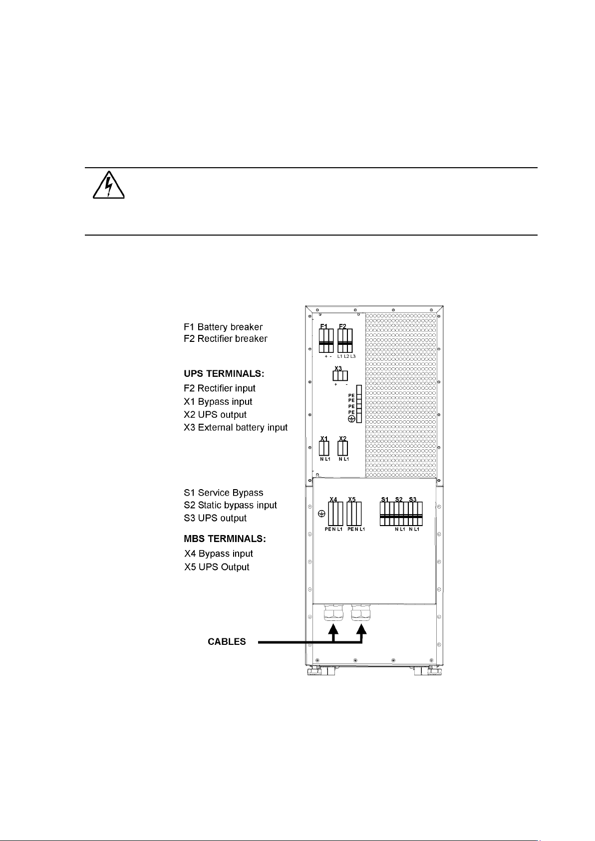
Figure 12. Location of the power terminals.
UPS 8 – 15 kVA, 230V 50/60 Hz output
User’s Guide
1022403
Revision D
14
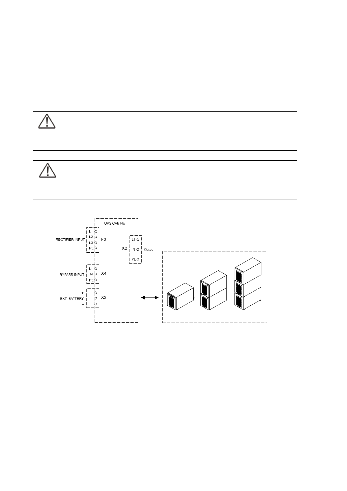
The UPS unit has the following power connections:
• Three-phase (L1, L2, L3) and protective earth (PE) connection for the rectifier input
or
Single-phase (L1), Neutral (N) isolated connection point (bypass N is used in the rectifier)
and protective earth (PE) connection for the rectifier input.
• Single-phase (L1), Neutral (N) and protective earth (PE) connection for the bypass input
• Single-phase (L1), Neutral (N) and protective earth (PE) connection for the load output
• Plus (+), minus (-) and protective earth (PE) connection for the external batteries
Note!
The rectifier requires a Neutral to operate. It’s connected internally from the bypass
terminal to the rectifier, see wiring diagram.
Note!
Care needs to be taken to ensure that the input supply neutral reference is not
disconnected whilst the UPS is in service.
Figure 13. Power terminals found in UPS units.
Power cables and protective fuses
Always use copper cable types to fit terminals with approximately 1.5 Nm torque for different
load currents. The Cu cable sizing is based on multi-core cables laid in conduits/trunkings on the
wall or on the floor (installation procedure C), ambient temperature 25°C, PVC insulation, surface
temperature up to 70°C. Cables of several UPS can be installed in parallel to each other.
Standards SFS 6000-5-52 (2002) and IEC 60364-5-52 (2001-08) “Electrical installations of buildings”
with normal 1.7 x Neutral conductor rating for IT loads are used as a sizing guide. For any
other conditions, size the cables according to the local safety regulations regarding installation
environment, appropriate voltage and currents of the UPS.
Fuses are sized according to local safety regulations, appropriate input voltage and the rated current
of the UPS. Therefore, protect the input and bypass cables with gG (gL) fuses or B-C-D type of circuit
breakers against overload and short-circuit.
UPS 8 – 15 kVA, 230V 50/60 Hz output
User’s Guide
1022403
Revision D
15
Contact the manufacturer’s authorised agent or the local office for assistance at fuse and cable
sizing. Refer to the recommended cable and fuse ratings in the below table.
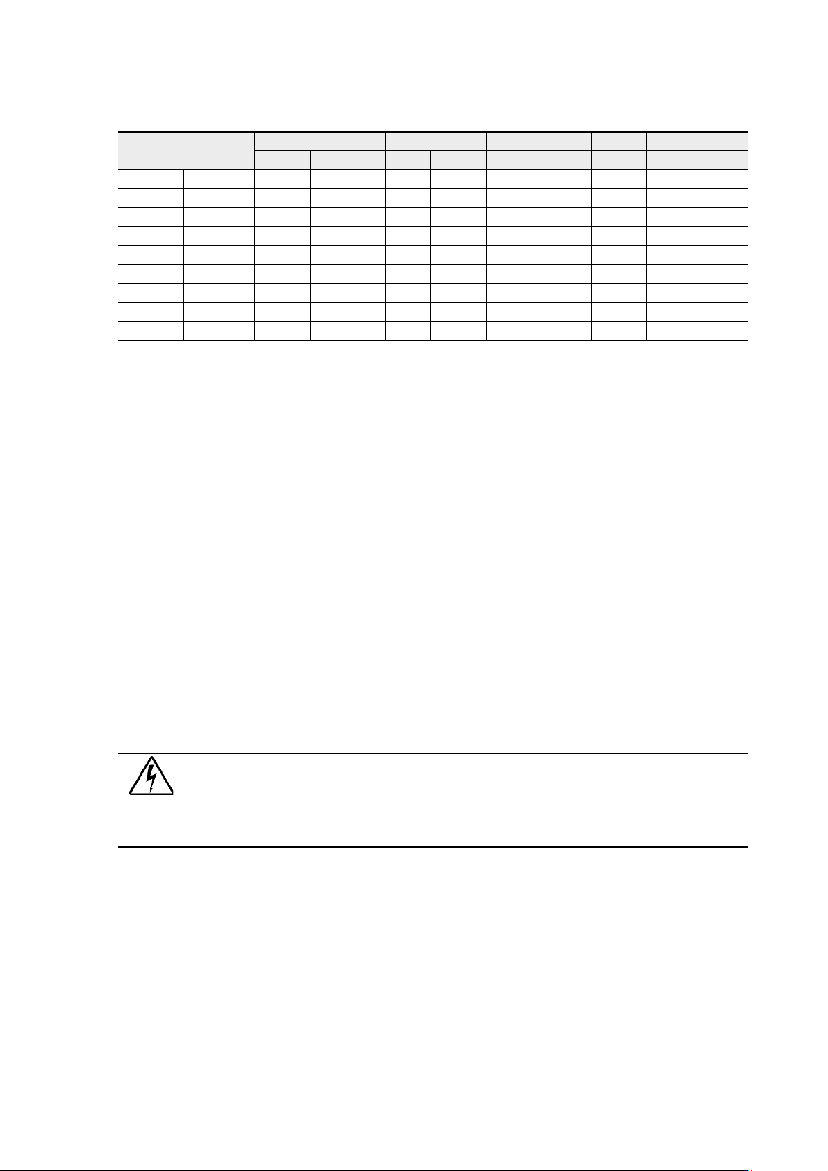
Table 14. Cable and fuse ratings for the different UPS ratings
(*With optional limited charging feature at low input and high kW load, see User Settings)
Wiring procedure
The power cable terminals are located in the back of the UPS unit. The service personnel is
responsible for the correct electrical installation. They must be authorised by the manufacturer.
The installation procedure:
1. Remove the cover(s) of the terminal box of the power cables with a screwdriver.
Refer to the dimensional drawing for the correct location at the back of the unit.
2. Slide the cables through the grommets of the connection box.
3. Connect the conductors of the rectifier and bypass input cables to the proper terminals.
With single phase unit it is recommended to use the same phases for rectifier and bypass
inputs.
4. Connect the conductors of the load cable to the proper terminals.
5. Connect the conductors of an external battery cabinet cable to the external battery +,
- and PE terminals. Check for the correct polarity.
See External Battery Cabinet (EBC) installation procedure.
Warning!
If available, the internal battery has to be disconnected first because the external
battery terminals are hazardous due to the parallel battery string.
6. Secure the cables with the grommets in the connection box.
7. Fasten the cover of the terminal box with a screwdriver.
The IEC/EN 62040-1 safety instructions require the fitting by the user of a warning label on all
primary power isolators installed remote from the UPS area. The warning label for electrical
maintenance personnel shall carry the following wording or equivalent:
“ISOLATE UNINTERRUBTIBLE POWER SUPPLY (UPS) BEFORE WORKING ON THIS CIRCUIT.”
A readily accessible disconnect device shall be incorporated in the building installation wiring
as shown in diagrams.
UPS rating
Input Bypass Load PE Battery
Fusing Cable Fusing Cable Cable I nom Cable Cable Fusing
8 kVA 3-phase 3x16 A 3x2.5 mm² 50 A 10 mm² 10 mm² 34.8 A 10 mm² 10 mm² 50 A
1-phase 50 A 10 mm² 50 A 10 mm² 10 mm² 34.8 A 10 mm² 10 mm² 50 A
10 kVA 3-phase 3x16 A* 3x2.5 mm² 50 A 10 mm² 10 mm² 43.5 A 10 mm² 10 mm² 50 A
3-phase 3x20 A 3x4 mm² 50 A 10 mm² 10 mm² 43.5 A 10 mm² 10 mm² 50 A
1-phase 63 A 16 mm² 50 A 10 mm² 10 mm² 43.5 A 10 mm² 10 mm² 50 A
12 kVA 3-phase 3x25 A 3x6 mm² 63 A 16 mm² 16 mm² 52.2 A 16 mm² 10 mm² 50 A
15 kVA 3-phase 3x25 A* 3x6 mm² 80 A 25 mm² 25 mm² 65.2 A 16 mm² 10 mm² 50 A
3-phase 3x32 A 3x10 mm² 80 A 25 mm² 25 mm² 65.2 A 16 mm² 10 mm²
Maximum 3-phase 3x63 A 3x16 mm² 80 A 35 mm² 35 mm² 35 mm² 16 mm²