Eaton 9155 8-15 kVA.pdf - 第20页
UPS 8 – 15 kV A, 230V 50/60 Hz output User ’ s Guide 1 022403 Revision D 20 Figure 21. Wiring diagram of UPS S-model (1-ph rectifier) with integral MBS, (Norway) Figure 22. Wiring diagram of UPS S-model (1-ph rectifier), (…
UPS 8 – 15 kVA, 230V 50/60 Hz output
User’s Guide
1022403
Revision D
19
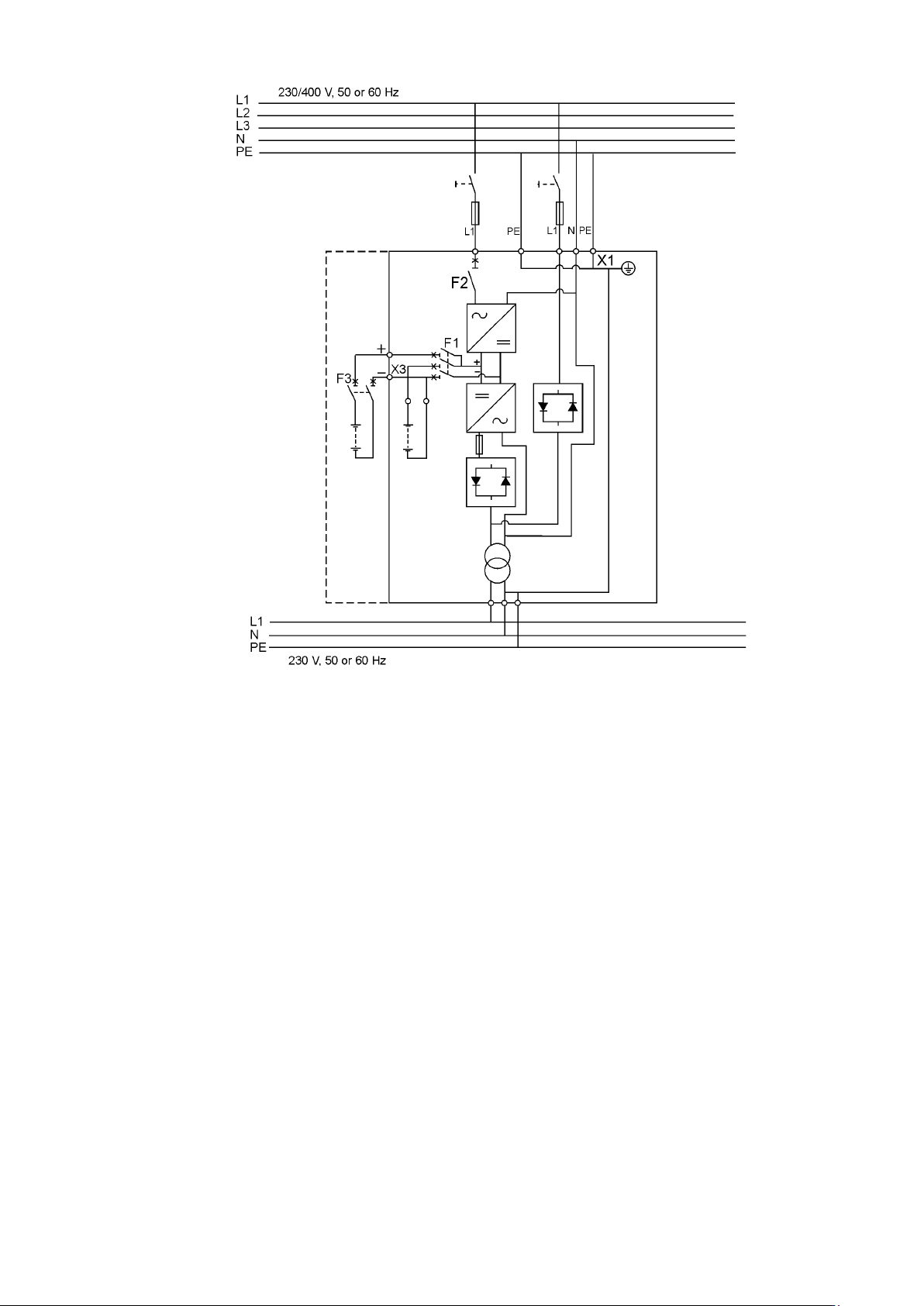
Figure 20. Wiring diagram of UPS ST-model (1-ph rectifier).
UPS 8 – 15 kVA, 230V 50/60 Hz output
User’s Guide
1022403
Revision D
20
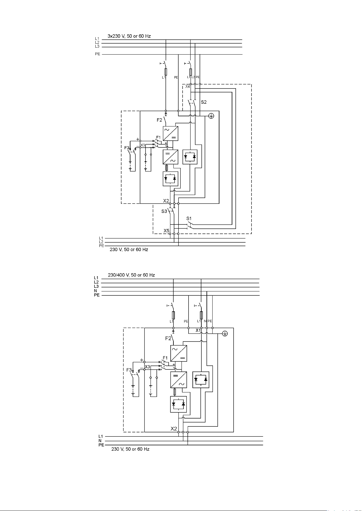
Figure 21. Wiring diagram of UPS S-model (1-ph rectifier) with integral MBS, (Norway)
Figure 22. Wiring diagram of UPS S-model (1-ph rectifier), (Norway)
Note!
Site wiring fault must be
disabled from LCD
User Settings menu.
Note!
Site wiring fault must be
disabled from LCD
User Settings menu.
UPS 8 – 15 kVA, 230V 50/60 Hz output
User’s Guide
1022403
Revision D
21
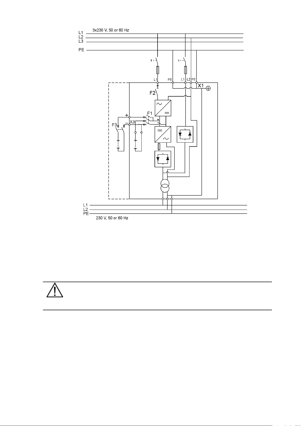
Figure 23. Wiring diagram of UPS ST-model (1-ph rectifier), (Norway)
External Battery Cabinet (EBC) installation procedure
The installation procedure is as follows:
1. The EBC is recommended to place next to the UPS unit.
Note!
Do not place EBC on the UPS unit.
2. The required minimum distance for UPS unit and EBC is ten millimetres, which is also
required distance between two EBCs.
3. Turn F1 battery breaker from the UPS unit in OFF position.
4. Check that the circuit breaker F3 of the EBC is in the OFF position. To minimise safety risk
disconnect one of the cable (+ or -) from battery string to break a battery circuit. Do not
remove the safety wire of the circuit breaker before all the wires are connected and the
installation of the whole system is ready. Remove plate A (See figure below.) on the rear
side of the EBC to connect cables to EBC’s terminal block X6. Bring cables outside from the
EBC by removing the cover plate B. Place the plate A back to the original position and use
cover plate B as a cable clamp.
Note!
Site wiring fault must be
disabled from LCD
User Settings menu.