Eaton 9155 8-15 kVA.pdf - 第40页
UPS 8 – 15 kV A, 230V 50/60 Hz output User ’ s Guide 1 022403 Revision D 40 7 . T urn ON S3 switc h to connect UPS output to load: 8. T urn OFF S1 switc h to disconnect bypass output: 9. Use LCD to transfer the UPS to no…
UPS 8 – 15 kVA, 230V 50/60 Hz output
User’s Guide
1022403
Revision D
39
8. Turn OFF the S2 switch to disconnect UPS bypass input:
9. Remount the locking plate of the S1-3 switches to the position to prevent the use of them.
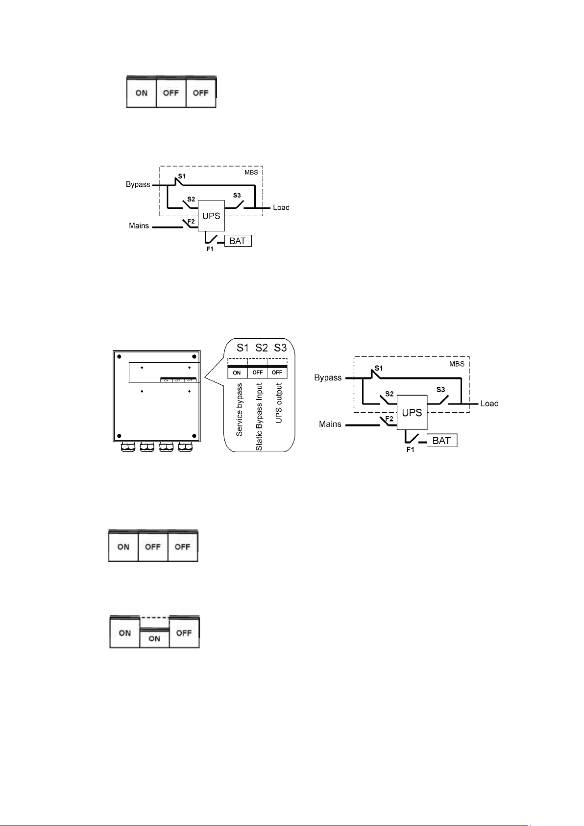
10. UPS is now in the mechanical bypass mode, see below:
Turn UPS from mechanical bypass to normal mode
The procedure to turn the UPS back to normal mode is described below.
Figure 41. The service (bypass supplying the load) positions of the three MBS switches.
No break transfer from Mechanical Bypass to normal mode:
1. The normal start position should be following:
2. Remove the locking plate of the S1-3 switches.
3. Turn ON S2 switch to connect bypass input to UPS:
4. Turn the F1 battery and F2 input breakers to ON position.
5. Use LCD to “Turn UPS on” and wait until fully started.
- Make sure the UPS is not displaying alarms or notices alarm with the green LED lit.
- You may verify the output voltage from the meters screen of the LCD.
6. Use LCD to transfer the UPS to internal static bypass. Remember to verify the transfer
before proceeding the next step.
UPS 8 – 15 kVA, 230V 50/60 Hz output
User’s Guide
1022403
Revision D
40
7. Turn ON S3 switch to connect UPS output to load:
8. Turn OFF S1 switch to disconnect bypass output:
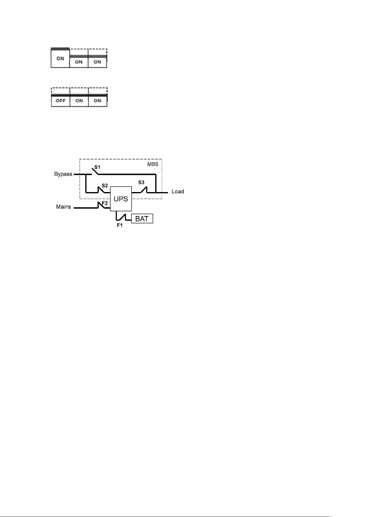
9. Use LCD to transfer the UPS to normal mode.
10. Remount the locking plate of the S1-3 swiches to the position to prevent the use of them.
11. UPS is now in Normal mode, see below:
UPS 8 – 15 kVA, 230V 50/60 Hz output
User’s Guide
1022403
Revision D
41
9. Parallel systems
Overview
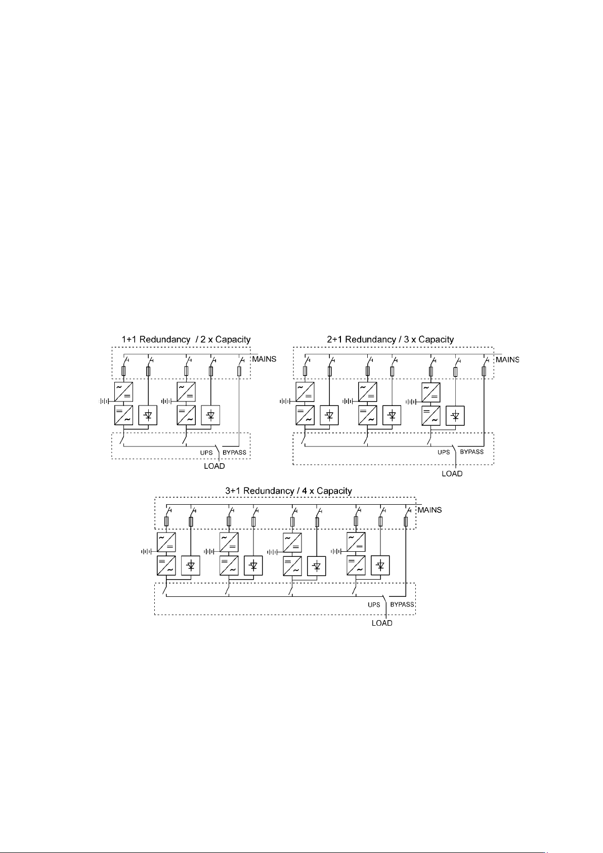
Parallel UPS configurations are recognised as either redundancy or capacity systems. The
redundancy system is used to improve the system reliability with N+1 redundant UPS module.
The capacity system for its part provides the maximum output power without focusing to the
highest system reliability.
A parameter selection is used to switch between the redundancy and capacity modes. It is
important to remember that the mode is affecting to the output power rating and overall system
reliability.
UPS modules of the parallel system share equally the load with Hot Sync
®
technology. The
parallel outputs can be combined in a System Parallel Module or cabinet. It is the system
component containing the obligatory service switches. Customer’s low-voltage distribution
panel can also be used instead of the System Parallel Module. In the redundancy system,
service switches enable the maintenance or service on an UPS module. In the capacity system,
one needs to have a common system bypass switch to do the maintenance or service without
safety hazards.
Figure 42. Parallel configurations with UPS modules
Field upgrading can be used to extend existing capacity/redundancy systems with UPS
modules. The upgrading must be carried out by service personnel from the manufacturer or
from an agent authorised by the manufacturer.