Eaton 9155 8-15 kVA.pdf - 第47页
UPS 8 – 15 kV A, 230V 50/60 Hz output User ’ s Guide 1 022403 Revision D 47 Note! XSlot Hot Sync car d has built-in ter mination r esist or enabled by a jumper J7 . The def ault jumper setting without t er mination r esi…
UPS 8 – 15 kVA, 230V 50/60 Hz output
User’s Guide
1022403
Revision D
46
XSlot Hot Sync card: installing and wiring
To enable parallel operation all the UPSs in the system need the XSlot Hot Sync card (see
Figure below) installed into an open XSlot on the front of the UPS (see chapter XSlot
communication from the UPS’s User’s Guide).
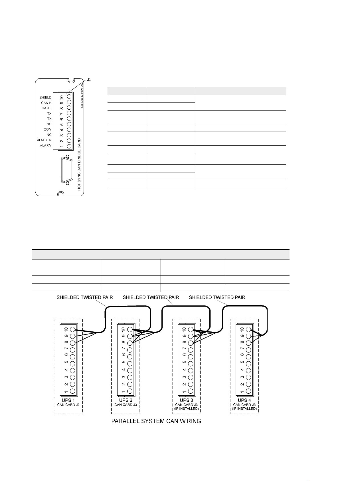
Figure 49. XSlot Hot Sync card and terminal interface
The Hot Sync communication wiring procedure should be done with shielded twisted pair
(STP) as presented in the figure below. The maximum length of the cable is 40 m with shield
connected to the terminal pin 10 from end of the both cables. Pay attention that you don’t mix
the polarity among the UPS modules.
Figure 50. Communication cabling wiring
Terminal J3 Name Description
1 Alarm
Programmable UPS alarm. Activated
by a remote dry contact closure
2 Alarm Rtn
3 Alarm Relay NC
Normally-closed contact opens when
UPS is on bypass.
4 Alarm Relay Com Bypass contact return.
5 Alarm Relay NO
Normally-open contact closes when
UPS is on bypass.
6 TX Remote Monitor Panel (RMP). Relay
Interface Module (RIM, or Supervisory
Contact Module (SCM) Connections.
7 TX
8 CAN L
Controller Area Network (CAN) Input
for parallel operation.
9 CAN H
10 Shield
Communication Wiring Termination
From UPS 1 CAN card To UPS 2 CAN card
To UPS 3 CAN Card
(If installed)
To UPS 4 CAN Card
(If installed)
J3-8 (L) J3-8 (L) J3-8 (L) J3-8 (L)
J3-9 (H) J3-9 (H) J3-9 (H) J3-9 (H)
UPS 8 – 15 kVA, 230V 50/60 Hz output
User’s Guide
1022403
Revision D
47
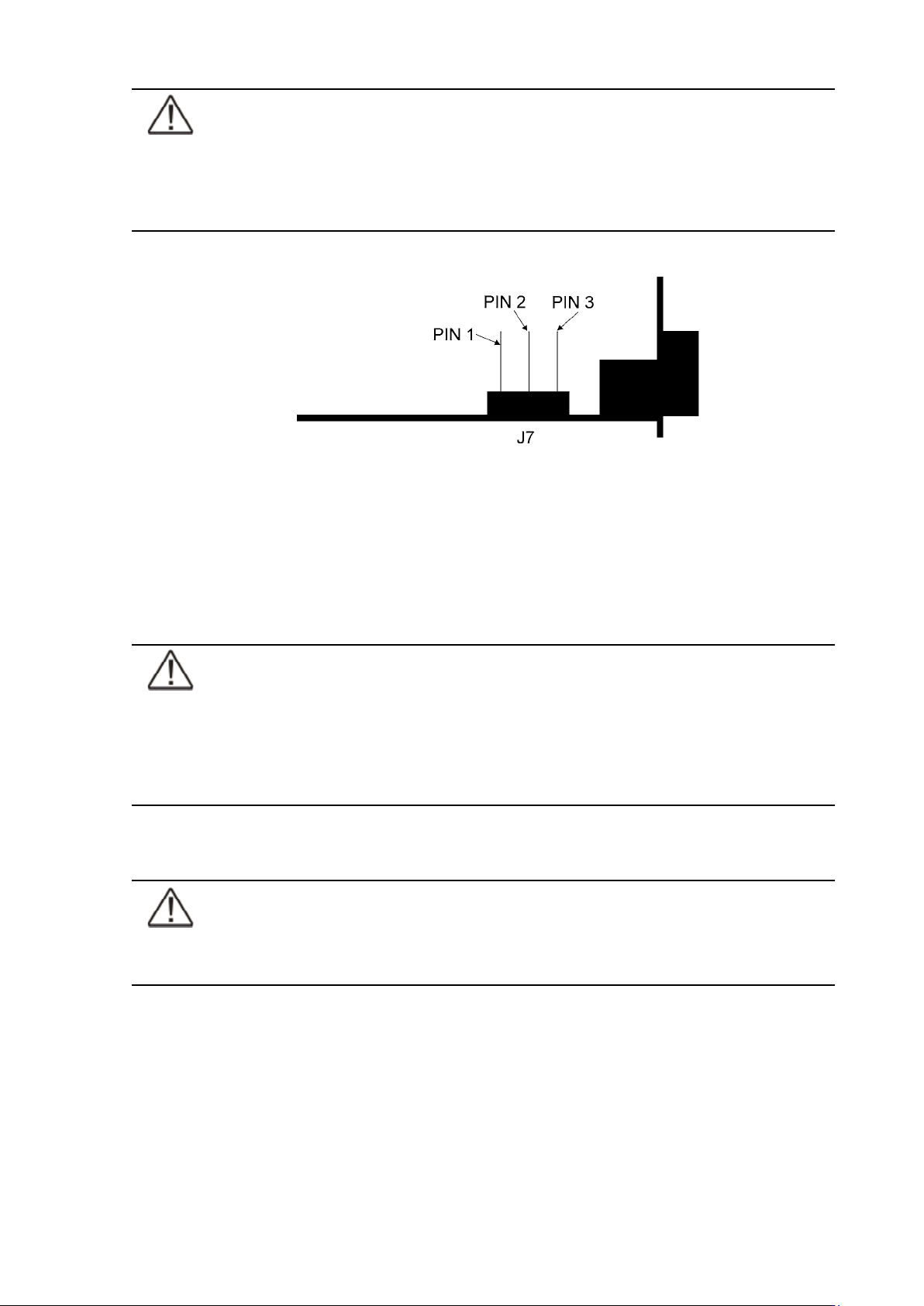
Note!
XSlot Hot Sync card has built-in termination resistor enabled by a jumper J7. The
default jumper setting without termination resistor is J7: Pin 2-3. The first and the
last UPS modules should have the termination resistor enabled by connecting Pins
1 and 2 with the jumper J7.
Figure 51. XSlot HotSync card and jumper settings: Resistor ON: PIN 1 and PIN 2 connected, No
resistor: PIN 2 and PIN 3 connected (default setting)
Parallel operations
Start-up
Note!
Before start-up make sure that UPS installations have been carried out correctly
and ground connections of both UPS units and parallel module have been
connected. Check also that the XSlot Hot Sync cards are installed correctly
and the communication line between UPSs is connected according to figure
Communication cabling wiring.
When installation is completed correctly the start procedure can be started.
Note!
If some settings are changed from User settings the same changes need to be done
separately to all of the UPSs in the system.
UPS 8 – 15 kVA, 230V 50/60 Hz output
User’s Guide
1022403
Revision D
48
Carry out the following procedure to each UPS you want to have in system
1. Turn the battery and input circuit breakers to ON position.
2. UPS will enter a stand-by mode and starts to charge batteries with a cooling fan
operational. Output is without the voltage in the stand-by mode.
3. Push any key of the control panel to enable the functions of the LCD screen
4. Select unit number in parallel system: Unit #1, Unit #2, Unit #3 or Unit #4. Select:
SETTINGS -> USER SETTINGS -> PARALLEL OPERATION SETTINGS -> PARALLEL UNIT
NUMBER
5. Select minimum units to support load: 0-4. Select: SETTINGS -> USER SETTINGS ->
PARALLEL OPERATION SETTINGS -> MINIMUM UNITS TO SUPPORT LOAD
Do the following item (item 6) only for one UPS, which belongs to the system
6. Return to main menu and select TURN SYSTEM ON
All the UPSs shall check their internal functions, synchronize to bypass and start to supply the
load.
Note!
After the first start the load sharing of the system needs to be calibrated. Before
starting the calibration the system needs to support some load.
7. Select: SETTINGS -> USER SETTINGS -> PARALLEL OPERATION SETTINGS -> START AUTO
CALIBRATION
Shutdown
While system is running and UPSs are supporting load, there are two different ways to perform
a shutdown. The user can select either to shutdown the whole system or only one UPS.
1. Select TURN SYSTEM OFF from the main menu => All the UPSs in the system will go to
stand-by mode.
2. Select TURN UPS OFF => Only the selected UPS will go to stand-by mode.
When UPS is in stand-by mode it still charges its batteries and uses cooling fans. Stand-by
mode possibles a fast restart. If some UPS or all the UPSs in the system need to be shutdown
completely, proceed to item 3.
3. Select TURN UPS OFF and press and hold
¿ button for 5 seconds. There shall be an
indication sound during the hold.
4. UPS shall do a shutdown routine.
5. Turn the battery and input circuit breakers to off position to finalise the shutdown
procedure.