OCP-02502-G - 第5页
EM 02502- 15-Nov-00 (c) Operator’s Manual * HOW TO USE THIS MANUAL * THIS PAGE EXPLAINS HO W THIS MANUAL IS ORGANIZED AND PRESENTED. PRIMARY DIVISIONS (as found in the Table of Contents) SECONDARY DIVISIONS (as found in …
VITRONICS REFLOW SOLDERING SYSTEMS
EM 02502-G 15-Nov-00 (c) PAGE Operator’s Manual
4
AUTHORIZED VITRONICS / SOLTEC SERVICE FACILITIES
The Vitronics- Soltec service sites are:
Europe
VITRONICS SOLTEC BV
Karolusstraat 20
4903 RJ Oosterhout
the Netherlands
tel. +31-162-483000
fax +31-162-483253
helpdesk@nl.vitronics-soltec.com
Germany
VITRONICS SOLTEC GmbH
An der Kohlerei 7
97828 Marktheidenfeld
Germany
tel. +49-9391-98820
fax +49-9391-988228
helpdesk@de.vitronics-soltec.com
Americas
VITRONICS SOLTEC Inc
2 Marin Way
Stratham, NH 03885
United States
tel. +1-603-772-7778
fax +1-603-772-9319
helpdesk@us.vitronics-soltec.com
Asia Pacific
VITRONICS SOLTEC PTE LTD.
10 Ang Mo Kio St 65
Techpoint Unit 01-05
Singapore 569059
tel. +65-484-3010
fax +65-484-1910
helpdesk@sg.vitronics-soltec.com
We can be contacted for service 24 hours a day
Please visit us at:
http://www.vitronics-soltec.com/
EM 02502- 15-Nov-00 (c) Operator’s Manual
* HOW TO USE THIS MANUAL *
THIS PAGE EXPLAINS HOW THIS MANUAL
IS ORGANIZED AND PRESENTED.
PRIMARY DIVISIONS (as found in the Table of Contents)
SECONDARY DIVISIONS (as found in the Table of Contents)
In the text throughout this manual you will find the following practice:
QUICK COOL DOWN is an option, title, or software selection and will be shown in
bold capitals.
ENTER is a keyboard key and will be shown in bold capitals.
VERY IMPORTANT INFORMATION IS SHOWN:
1) Bold
2) CAPITALIZED
3) IN ITALICS
4) Underlined
5) WITH A SHADED BACKGROUND
6) WITH A BOX AROUND IT
7) OR SOME COMBINATION OF 1 - 6 ABOVE
VITRONICS REFLOW SOLDERING SYSTEMS
EM 02502-G 15-Nov-00 (c) PAGE Operator’s Manual
6
OVEN CONTROL PANEL PUSHBUTTON SYMBOLS
NOTICE
WHEN “POWER TO PROCESS” IS INTERUPTED, PARTS OF THE OVEN ARE
ELECTRICALLY POWERED AND DANGEREROUS TO PERSONNEL !!!
Information is presented here only to explain the graphic symbols on the
“Oven Control Panels”, NOT to instruct on the Operation of the Oven.
Refer To The Appropriate Equipment Manual(s) For Proper Oven Operation
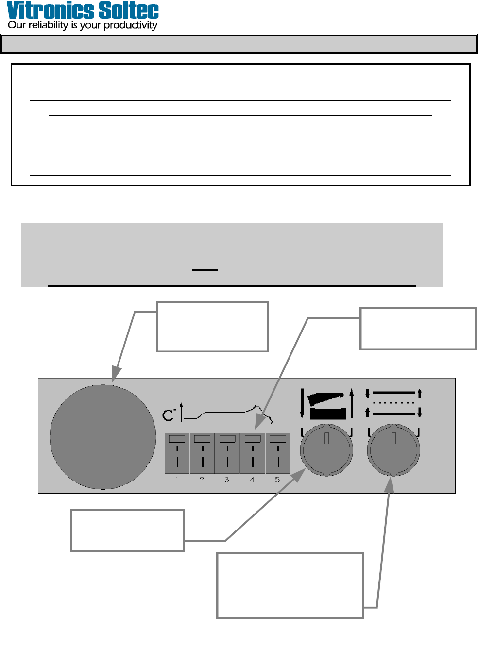
OFF-LOAD CONTROL PANEL
Attention
Some Oven Models may have differently shaped Control Panels
and may not have ALL the functions shown here.
The meaning of the symbols explained here are the same.
THERMOCOUPLE
INPUTS FOR OVEN
PROFILING
SELECTOR SWITCH
RAISES AND LOWERS
THE OVEN HOOD
SELECTOR SWITCH
ADJUSTS RAIL
and
CENTER BOARD SUPPORT
IN or OUT
EMERGENCY STOP
BUTTON (E-STOP)
INTERRUPTS POWER
TO PROCESS