TR7007M_SII_Hardware_en_v1-0-1.pdf - 第17页
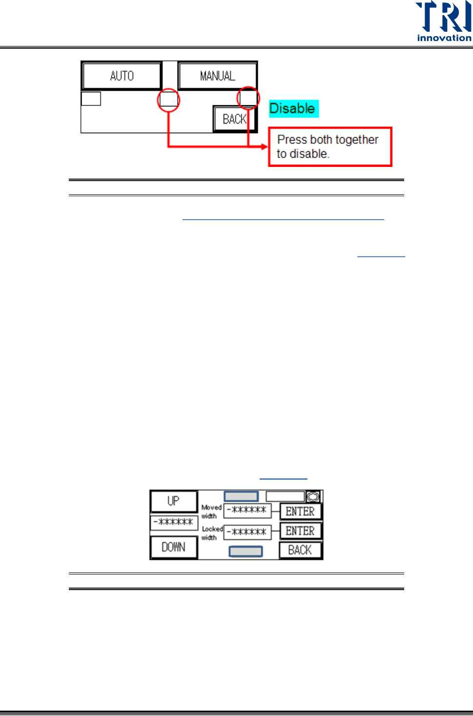
Test Research, Inc. TR7007M SII User Guide – Hardware 7 Figure 11 : Auto /M anual Convey or Adjust Hidde n B uttons -- Disable Press [ AUTO ] adjustment in Figure 8: Auto/Manual Convey or A djust and the conveyor width…
Test Research, Inc.
6 TR7007M SII User Guide – Hardware
Conveyor Width
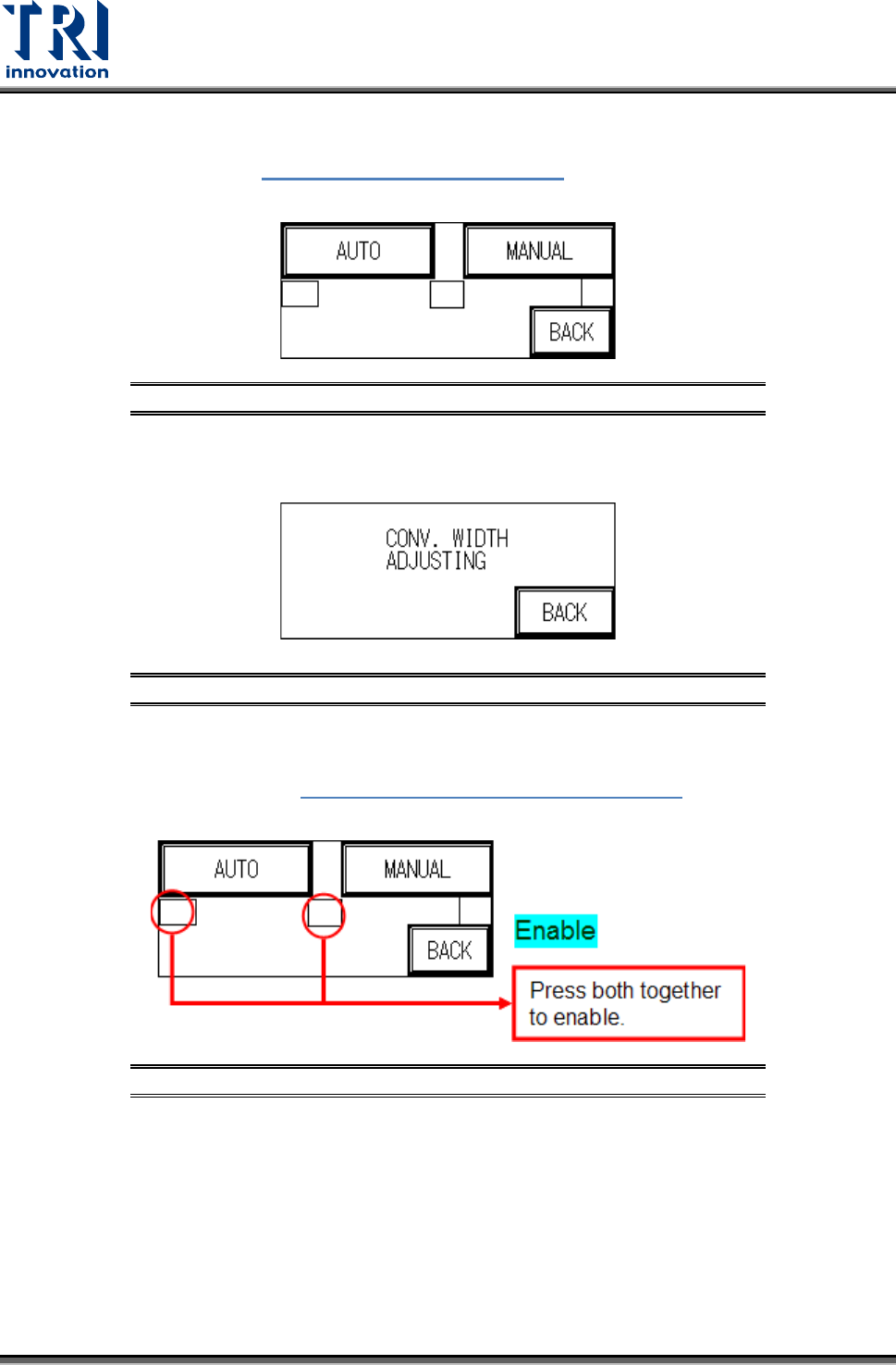
Press [CONV. WIDTH] in Figure 7: Other Settings Page 1
and [AUTO] or [MANUAL]
adjustment can be selected as shown in the following figure.
Figure 8: Auto/Manual Conveyor Adjust
MANUAL Adjustment: Press [MANUAL] to use the Conveyor Width Adjuster wheel at
the front of the conveyor to set the conveyor width.
Figure 9: Conveyor Width Adjustment
AUTO Adjustment (optional): To prevent PLC error due to no automatic conveyor
width device being installed when the PLC is set to AUTO CONV. WIDTH, two hidden
buttons are provided in Figure 8: Auto/Manual Conveyor Adjust
to Enable/Disable
the function. Only when in Enabled mode can AUTO adjustment be selected.
Figure 10: Auto/Manual Conveyor Adjust Hidden Buttons--Enable
Test Research, Inc.
TR7007M SII User Guide – Hardware 7
Figure 11: Auto/Manual Conveyor Adjust Hidden Buttons--Disable
Press [AUTO] adjustment in Figure 8: Auto/Manual Conveyor Adjust and the
conveyor width will return to the origin (machine origin) first. If this is the first setting
operation from the factory, once the initialization process has been completed, the
“Electrical Origin” must be set, with the [ORIGIN] point blinking in
Figure 12. The
machine type’s maximum testable board width can be adjusted here. Once the setting
is entered the PLC will automatically memorize that value.
Press [BACK] then perform the [RESET] operation, and the next time this display is
accessed, the [ORIGIN] point text will not blink. The test board width can now be set
according to the method described above. The settings for conveyor width can also be
set or read through the PC.
If the electrical origin needs to be set again, press the hidden buttons located at the
top-center and bottom-center of the HCI as shown in gray in the following figure. In
general, the [Moved width] and [Locked width] are the same. If users want to use two-
stage width function, the [Moved width] and [Locked width] should be set individually.
The steps of two-stage width are: the system uses [Moved width] when board-in; when
the board touches Sensor 3, the system adjusts the conveyor width to [Locked width]
and clamps the board. After inspecting, the system adjusts the conveyor width to
[Moved width] to exit. If the [Moved width] and [Locked width] are not the same, the
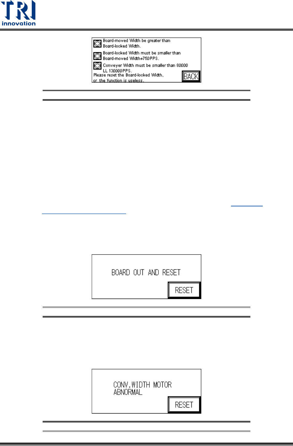
system will display the setting rules, such as
Figure 13, to avoid the error.
Figure 12: Auto Conveyor Width
Test Research, Inc.
8 TR7007M SII User Guide – Hardware
Figure 13: Auto Conveyor Width -- Rules of Two-Stage Function
Important Notes
All setting values prevent the entry of negative numbers.
The indicator in the top right corner is the machine [ORIGIN] Sensor. When the
indicator goes on after pressing the [UP] button it means the maximum width has
been reached. Below the hidden key in the top-center, the [-*******] is the current
conveyor width position (unit: 0.008mm/pps); Above key at the bottom-center, the
[-******] is the set conveyor width position (unit 0.008mm/pps).
If the two-stage conveyor width function is enabled, PLC should collocate with SPI
main program.
When the conveyor width reset is in action, if there is a board to be tested located
over SENSORS 1, 2, 3, or 4 then the alarm will go off and show
Figure 15:
Conveyor Width Abnormal. Please remove the board before executing the
Reset operation.
If the conveyor width operation times out before reaching the set position, an
alarm will ring and show the “Remove Board” display (below). Please check the
conveyor width parts to see if they are correctly installed or malfunctioning.
Figure 14: Remove Board Message
NOTE: If an automatic conveyor width device is not installed and the function is
accidentally triggered, this will cause a PLC Error that cannot be Reset. The
PLC’s error indicator will show a red light. If this happens then the machine power
must be restarted. The PLC option must then be switched to RUN then back to
PROG, with CONV. WIDTH’s AUTO disabled and changed to MANUAL.
Figure 15: Conveyor Width Abnormal