TR7007M_SII_Hardware_en_v1-0-1.pdf - 第19页
Test Research, Inc. TR7007M SII User Guide – Hardware 9 Li ght In Figure 7: Other Settings Page 1 , select [ LIGHT ] t o set the Three Colored Indicator Light Display ( see the following figure). First press to highl i…
Test Research, Inc.
8 TR7007M SII User Guide – Hardware
Figure 13: Auto Conveyor Width -- Rules of Two-Stage Function
Important Notes
All setting values prevent the entry of negative numbers.
The indicator in the top right corner is the machine [ORIGIN] Sensor. When the
indicator goes on after pressing the [UP] button it means the maximum width has
been reached. Below the hidden key in the top-center, the [-*******] is the current
conveyor width position (unit: 0.008mm/pps); Above key at the bottom-center, the
[-******] is the set conveyor width position (unit 0.008mm/pps).
If the two-stage conveyor width function is enabled, PLC should collocate with SPI
main program.
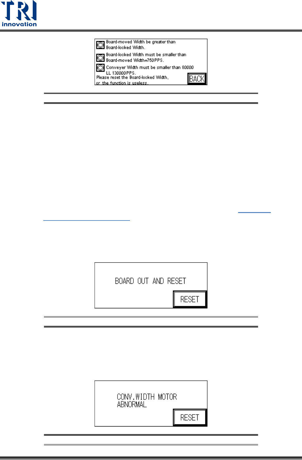
When the conveyor width reset is in action, if there is a board to be tested located
over SENSORS 1, 2, 3, or 4 then the alarm will go off and show
Figure 15:
Conveyor Width Abnormal. Please remove the board before executing the
Reset operation.
If the conveyor width operation times out before reaching the set position, an
alarm will ring and show the “Remove Board” display (below). Please check the
conveyor width parts to see if they are correctly installed or malfunctioning.
Figure 14: Remove Board Message
NOTE: If an automatic conveyor width device is not installed and the function is
accidentally triggered, this will cause a PLC Error that cannot be Reset. The
PLC’s error indicator will show a red light. If this happens then the machine power
must be restarted. The PLC option must then be switched to RUN then back to
PROG, with CONV. WIDTH’s AUTO disabled and changed to MANUAL.
Figure 15: Conveyor Width Abnormal
Test Research, Inc.
TR7007M SII User Guide – Hardware 9
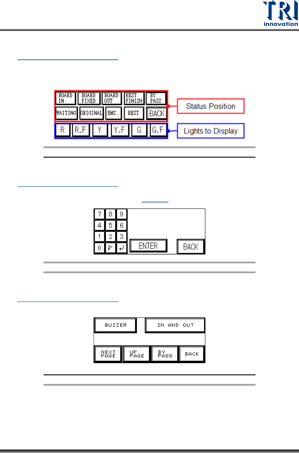
Light
In Figure 7: Other Settings Page 1
, select [LIGHT] to set the Three Colored Indicator Light
Display (see the following figure). First press to highlight the status position to set, then
select the lights to display for that step. If no settings are made then the factory defaults will
be used.
Figure 16: Indicator Lights
Test Count
In Figure 7: Other Settings Page 1
, select [TEST COUNT] to set the number of test cycles
to perform in TEST mode (below figure). If set to 0, then the number of cycles is infinite.
Press [BACK] to return to the Startup page (
Figure 3).
Figure 17: Set Test Count
Other Settings Page 2
In Figure 7: Other Settings Page 1
, select [NEXT] to display page 2 of the Settings menu.
Options available are:
Figure 18: Other Settings Page 2
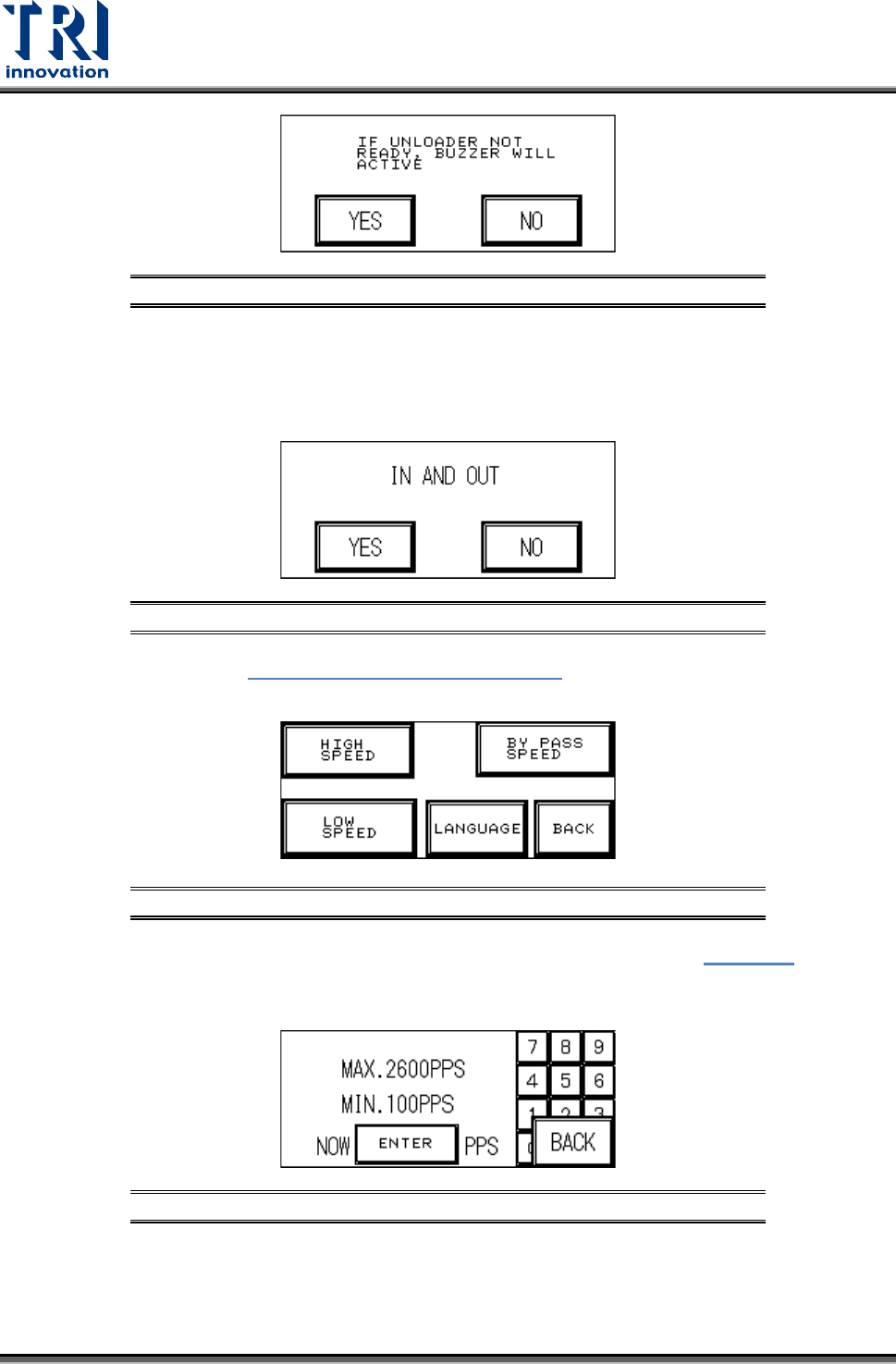
BUZZER: Confirm if an alarm buzzer will sound to warn the operator if the Unloader is
not ready to avoid causing a board blockage at the Loader.
Test Research, Inc.
10 TR7007M SII User Guide – Hardware
Figure 19: Confirm Buzzer
IN AND OUT: Choose simultaneous In and Out to load a board while another board is
being unloaded (the test board length must be less than 200mm or there may be an
issue with board overlap). If NO is chosen then a board must be fully unloaded before
another is loaded.
Figure 20: Choose Simultaneous In & Out
Next Page: From Figure 18: Other Settings Page 2, select [NEXT PAGE]. The five
options available are:
Figure 21: Other Settings Page 3
HIGH SPEED:This is the normal I/O speed. Press [ENTER] at Figure 22 to set
this speed. The speed range has an upper limit of 2600PPS and lower limit of
100PPS. Default setting is 2000.
Figure 22: High Speed Setting
BYPASS SPEED: This is the bypass speed. Press [ENTER] at the following
figure to set this speed. The speed range has an upper limit of 2600PPS and
lower limit of 100PPS. Default setting is 2000.