TR7007M_SII_Hardware_en_v1-0-1.pdf - 第32页
Test Research, Inc. 22 TR7007 M SII User Guide – Hardware Figure 59 : Confirm to Open the Suppor t Pin Function 3.2.6 R eset Press [Reset] t o return to the standby sc reen ( Figure 37 , Fi gure 38 , or Figure 39 ). 3.3 …
Test Research, Inc.
TR7007M SII User Guide – Hardware 21
Y113(OUT)
REVERSE CONVEYOR MOTOR (used by TR7100),
2D LED1 (used by TR7600/L)
Y114(OUT)
DRCH POWER (used by TR7100/ TR7100EP)
Y115(OUT)
DOS PC POWER(used by TR7100/ TR7100EP)
Y116(OUT)
BRAKE CONVEYOR WIDTH
Y117(OUT)
NOTIFY PC TEST (used by TR7100EP/TR7600)
Y118(OUT)
NOTIFY PC EMERGENCY STOP
(used by TR7100EP/TR7600)
Y119(OUT)
NOTIFY PC READ BARCODE
(used by TR7100EP/TR7600)
Figure 56: X-Y Table I/O Signals
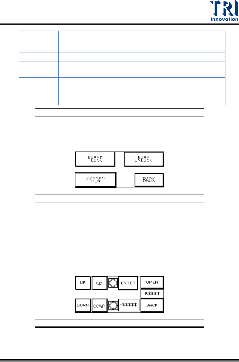
3.2.5 Board Holder
Press [BOARD LOCK] or [BOARD UNLOCK] to test if the Board Holder is working
normally; press [BACK] to return to Figure 43: DEBUG Display.
Figure 57: Board Holder Display
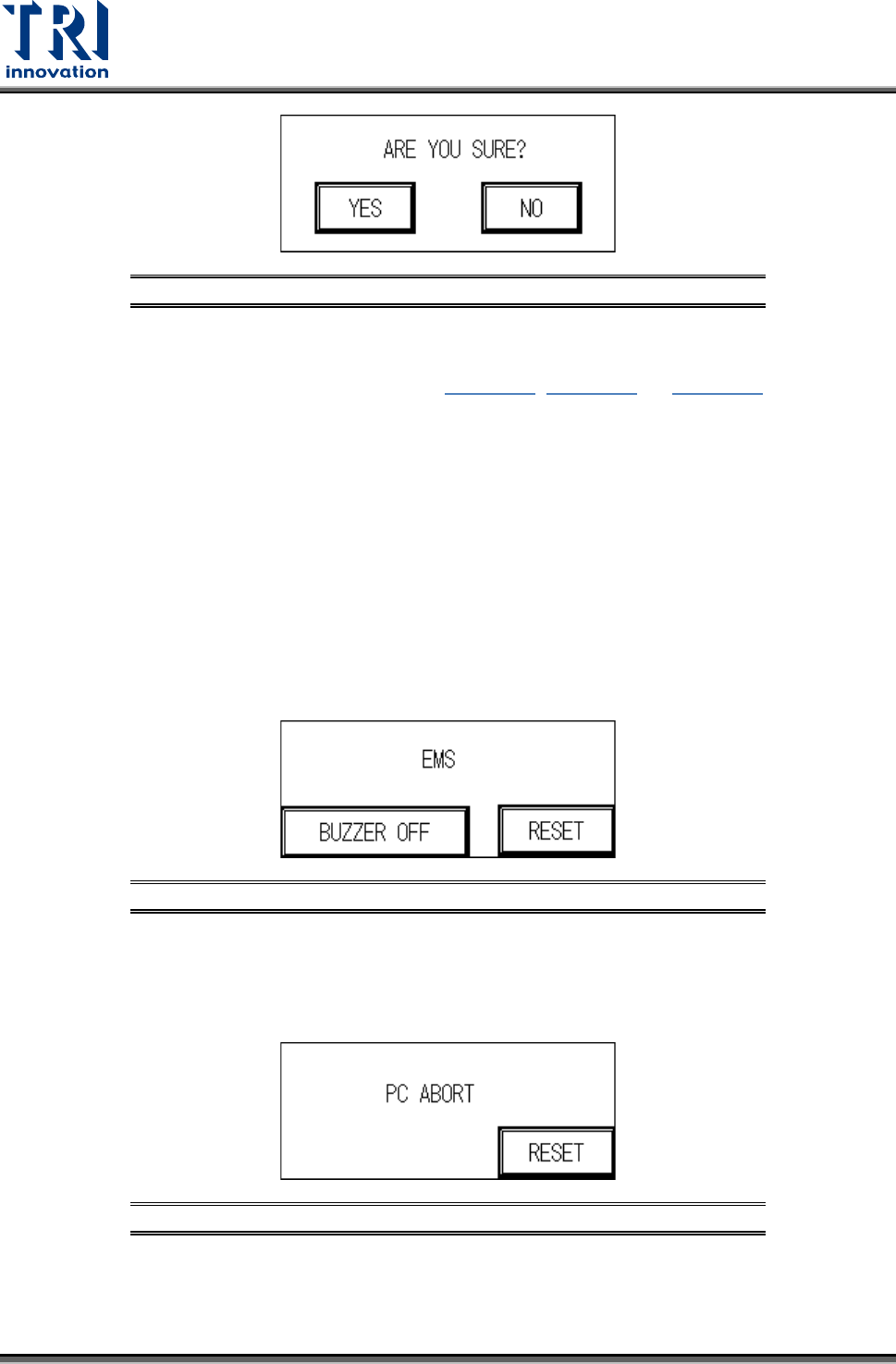
SUPPORT PIN: Place the candidate board at the loading Sensor and press ENTER. Wait
until the Support Pin is in position then press the [UP/DOWN] button to gradually adjust it
up and down. First it needs to be moved to the lowest position (the lower limit indicator
light will be lit) and then press [RESET]. Now press [UP] to adjust it to the location to
support the candidate board. The setting value will be shown at [-******]. When setting is
complete press [BACK]. If this accessory was not purchased or not in use, please make
sure that you press [OPEN] and then choose [NO] (or it cannot be reset). To the right of
the [UP/DOWN] buttons are their respective upper and lower elevation limit Sensor
indicator lights. If the indicator light is lit, it means the limit has been reached. The smaller
[up] and [down] mean to fine tune the position. Press once means to move 100pps.
Figure 58: Support Pin Setting
Test Research, Inc.
22 TR7007M SII User Guide – Hardware
Figure 59: Confirm to Open the Support Pin Function
3.2.6 Reset
Press [Reset] to return to the standby screen (Figure 37, Figure 38, or Figure 39
).
3.3 HCI Alert Messages and Causes
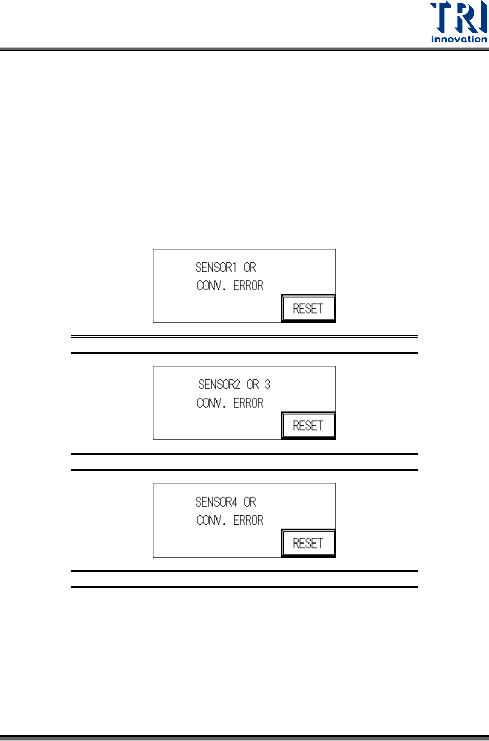
3.3.1 EMS
User can press [BUZZER OFF] to turn off the buzzer and check the machine. After
troubleshooting, user can press [RESET] to return to the Standby screen. If the
troubleshooting is not finished and user still presses [RESET], the screen will go back to the
EMERGENCY STOP screen again. The possible causes are:
1) The emergency stop button has been pressed.
2) The front door or rear door has been opened. To deactivate this function, set the interlock
switch on the inside of the front door to OFF. Please pay attention to safety
Figure 60: Emergency Stop Display
3.3.2 PC Abort
PC sends the ABORT message, then user has to check if the link between PC and PLC is
normal.
Figure 61: PC Abort Display
3.3.3 Sensor or Conv. Error
The reasons for a Sensor or Conv. Error may be:
Test Research, Inc.
TR7007M SII User Guide – Hardware 23
1) SENSOR Always On:
The Sensor sensitivity range is too long.
The candidate board has been covering the sensor for too long, there may be a jam or the
conveyor belt may not be operating.
2) SENSOR Always OFF:
The Sensor sensitivity range is too short.
The candidate board has not been detected by the sensor for too long, there may be a
jam or the conveyor belt may not be operating.
3) Conveyor Error: Motor or Motor Driver Malfunctioning, or Belt Detached.
Figure 62: Sensor 1 Error
Figure 63: Sensor 2 or 3 Error
Figure 64: Sensor 4 Error
3.3.4 UP-Holder Motor Error
The reasons for a Holder Motor Error may be:
1) Sensor 5 or 6, ON/OFF error: Incorrect detection height adjustment.
2) Motor Error: Motor or Motor Driver malfunction.