TR7007M_SII_Hardware_en_v1-0-1.pdf - 第42页
Test Research, Inc. 32 TR7007 M SII User Guide – Hardware 3.6.2 Four A xis Contr oller (FP2 - PP4) Unit Status Display LEDs LED Descripti on LED On LED Off A Pulse out put sign al A Blinking d uring p ulse output During …
Test Research, Inc.
TR7007M SII User Guide – Hardware 31
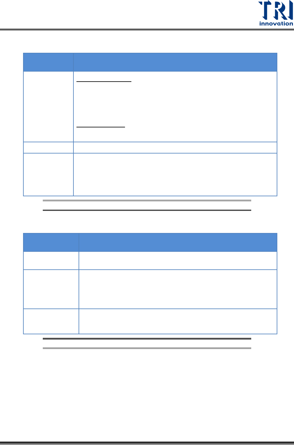
Initialize/Test Switch
SWITCH
POSITION
OPERATION MODE
INITIALIZE (up)
In the PROG. mode:
The contents of the operation memory are initialized. However, the
system register (including the I/O map) and the program are not
initialized. If the error of self-diagnostic error code 42 or lower is
occurred, the special internal relays R9000 to R9008 and the special
data register DT90000 are not cleared.
In the RUN mode:
Operation errors, remote I/O system errors, and battery errors are
cleared.
(center)
The switch should normally be left in this position.
TEST (down)
Setting this switch to the downward position in the PROG. mode,
accesses the TEST mode. Switching to the RUN mode in this status,
initiates test operation.
To return from the TEST mode to normal operation, return this switch to
the center position in the PROG. mode.
Figure 80: CPU(FP2-C1) – Initialize/Test Switch
Mode Selector
SELECTOR
POSITION
OPERATION MODE
RUN (up)
This sets the RUN mode. The program is executed, and operation
begins.
REMOTE (center)
This enables operation to be started and stopped from a programming
tool. At the stage where the selector is changed, when switching from
the PROG. to the REMOTE mode, the system remains in the PROG.
mode and when switching from RUN mode to the REMOTE mode, it
remains in the RUN mode.
PROG. (down)
This sets the PROG. mode. In this mode, programming can be done
using tools, the test operation mode can be accessed and the
operation memory can be initialized using the initialize/test switch.
Figure 81: CPU(FP2-C1) – Mode Selector
Test Research, Inc.
32 TR7007M SII User Guide – Hardware
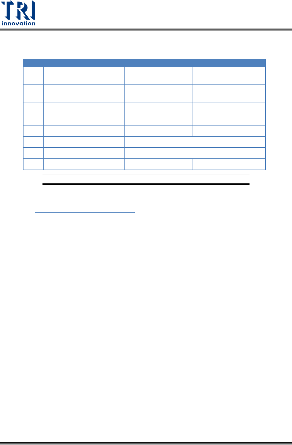
3.6.2 Four Axis Controller (FP2-PP4) Unit Status Display LEDs
LED
Description
LED On
LED Off
A Pulse output signal A
Blinking during pulse
output
During stop
B Pulse output signal B
Reverse direction
command
Forward direction
command
CL
Counter clear signal output
Output: on
Output: off
D
Near home status
On
Off
Z
Home input status
On
Off
PA
Pulser signal input
Displays input status of pulser input signal A.
PB
Pulser signal input
Displays input status of pulser input signal B.
ERR
Setting value error
Setting value: error
Setting value: normal
Figure 82: FP2-PP4 – Operation Status Display LEDs
3.6.3 I/O (FP2-XY64D2T & FP2-Y16P) Unit
Refer to Figure 56: X-Y Table I/O Signals
Test Research, Inc.
TR7007M SII User Guide – Hardware 33
4 CONVEYOR
4.1 Architecture and Function
The main function of the conveyor belt is to transport a PCB or a multi-board panel and
complete the loading/unloading operation. Long term operation may lead to the conveyor belt
not being fully set on the drive axle, so users are advised to check that the front and back
conveyor belts are set properly on their axles before beginning operations. If the belt needs
to be replaced, first fit the belt on to the drive axles on both ends before fitting it in order over
the inner axles.
4.2 Sensor Adjustment and Replacement
1) Sensors 1 & 4 (Loading/Unloading Sensors): Use the adjustment rod to adjust the Sensor
sensitivity until the indicator light is lit. (If there is an obstruction over the Sensor, the
indicator light will be lit, if there is no obstruction over the Sensor, the indicator will be off.)
Then gradually reduce it until the indicator light goes off. This will be the optimal sensor
status for Loading/Unloading.
2) Sensors 2 & 3 (Brake and Stop Sensors): Adjustment method is the same as above, but
the LED light base must be moved into position above the Sensor to check if the LED
light base will interfere, causing faulty operation. If interference does occur, the Sensor’s
sensitivity needs to be reduced until it is no longer affected by the LED light socket but
still able to sense the candidate board.
3) Sensors 5 & 6: (Holder Motor Sensors): Lower the holder mechanism to its lowest
position along with the Sensor. Move the Sensor upwards until the indicator light is lit,
then move it slowly downwards again until the indicator light goes off for the correct
setting.
4) Replacement: If a Sensor is not working, then the Sensor’s sensitivity should be re-
adjusted. If it still does not operate, replace with a new sensor. Replacement Method: first
disconnect the Sensor connector, and then remove the Sensor. Attach the new Sensor
then connect and secure the Sensor’s connectors. Once replacement is complete, adjust
as directed in the relevant adjustment method.
4.3 Linking with Loader and Unloader
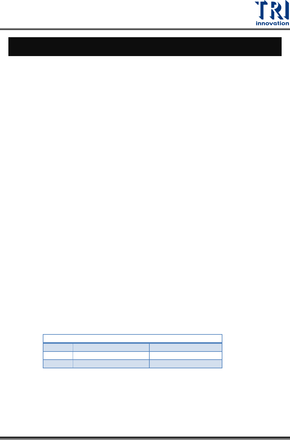
4.3.1 Loader Connection
PORT1 – UP LINE
Y104
Black (1) / Green (2)
Ready
X8A
Red (3) / Blue (4)
Board Available
X8B
Yellow (5) / White (6)
Spare
Located below the power supply socket in the back of the equipment is I/O PORT1. Connect
the connector, and there are three sets of different colored wire pairs at the connector end.
These are: Black-Green (Y104) for requesting board from Loader, Red-Blue (X8A) reserved
INPUT connector and the Yellow-White (X8B) reserved INPUT connector. Connect the
Black-Green connector to the Loader Board Request connection. (We use the standard
SMEMA signal. If this is different due to differences in manufacturer, contact the front stage
manufacturer to acquire the connection data.)