TR7007M_SII_Hardware_en_v1-0-1.pdf - 第62页
Test Research, Inc. 52 TR7007 M SII User Guide – Hardware P ROBLEM P OSSIBL E C AU S E S OLUTION Motor does not work a t all 1. Motor m alfunc tion 2. W iring probl em 1. Replace m otor 2. Check to see if wiring * 1 is m…
Test Research, Inc.
TR7007M SII User Guide – Hardware 51
9.2 Automatic Conveyor Width
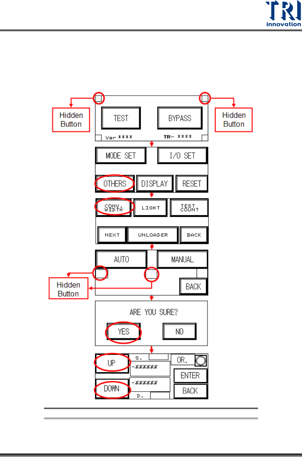
First perform a test manually (the two hidden buttons must be pressed simultaneously, the
setting procedure is as shown in the figures below) and depending on the results, refer to the
table below and troubleshoot.
Figure 97: Automatic Conveyor Width Troubleshooting Process
Test Research, Inc.
52 TR7007M SII User Guide – Hardware
PROBLEM POSSIBLE CAUSE SOLUTION
Motor does not work at
all
1. Motor malfunction
2. Wiring problem
1. Replace motor
2. Check to see if wiring *1 is
malfunctioning or detached.
Current in Motor, but
Does Not Run
1. Mechanical obstruction
2. Incorrect driver setting
1. Remove obstruction
2. Check current and switch
settings.
Motor reaches end
limit but does not stop
1. Incorrect limit sensor position
2. Limit sensor malfunction
1. Check installation position of
sensor
2. Replace sensor
Figure 98: Motor Troubleshooting Matrix
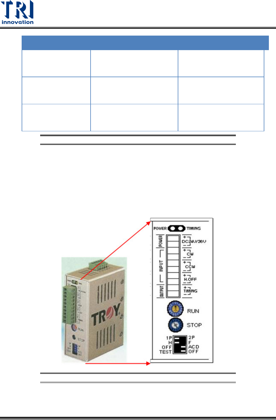
9.2.1 Stepping Motor Driver Problem
1) RUN and STOP adjustment
There are two variable resistors located below the Driver. There is a cross-shaped location
where the variable resistor can be adjusted. Use the adjustment rod to turn the arrow at the
cross location, turn in a clockwise direction to increase.
Figure 99: Back Panel of Stepping Motor
Test Research, Inc.
TR7007M SII User Guide – Hardware 53
2) Replacement
Motor Driver: First turn off the power then remove the two sets of wires and two DC +24V
power supply cables from the Driver. There is a screw at the top and bottom of the driver.
Remove the screws to install the new Driver. Once replacement is complete, reconnect the
wiring and power cables. After replacement re-adjust the driver using the proper adjustment
method.
3) Wiring Diagram
For System Wiring Diagrams, please refer to the separate Wiring
Diagram manual.