TR7007M_SII_Hardware_en_v1-0-1.pdf - 第83页
Test Research, Inc. TR7007M SII User Guide – Hardware 73 Figure 112 : Finish F in ding D SP C ard 3) Scanning f or Extension Devices Once the entire system connection is es tablished successfully , the program wil l scan…
Test Research, Inc.
72 TR7007M SII User Guide – Hardware
9.6.2 EzLINK
EzLink is a suite of software tools to test if a serial connection is working properly.
EzLink is a diagnostic software tool often used during system setup. In case of any system
error, the EzLink software can easily identify whether the problem is related to hardware or
software.
Once the EzLink program is running, it will start with detecting all extension devices that are
currently on-line. These devices will then be classified as either I/O type or Motion type. From
the complete list of control modules identified, it is therefore easy to verify if the system is
working properly or not. It is also possible to perform a functional test just by clicking on the
individual extension device.
Test Procedure:
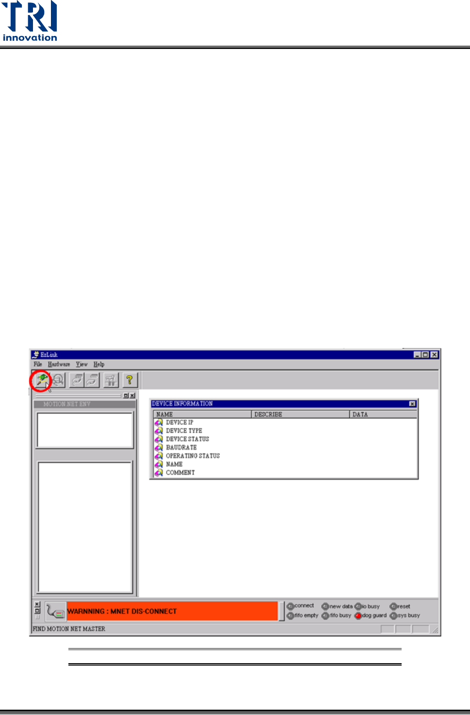
1) Open EzLink
For Windows XP, 32bit computer (TR7550), the execute file is in
[D:\SYNTEK\TRI_0331_EzLink_32\EzLink.exe]
For Windows XP, 64bit computer (TR7066/7007/7700), the execute file is in
[D:\SYNTEK\X64_Driver_DLL_Dev\EzLink_64.exe]
2) Press [Hardware Search] button to find DSP card. Refer to the following figures.
Figure 111: Hardware Search
Test Research, Inc.
TR7007M SII User Guide – Hardware 73
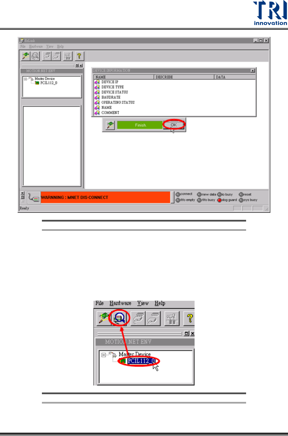
Figure 112: Finish Finding DSP Card
3) Scanning for Extension Devices
Once the entire system connection is established successfully, the program will scan for all
extension devices to identify the total quantity, current status, availability, and the
characteristics of these devices.
Refer to the following figure. Select [PCIL112_0] under the Master Device then press
[REFLASH RING] to search all Slave Module of X axis.
Figure 113: EzLink Scan Device Screen
Test Research, Inc.
74 TR7007M SII User Guide – Hardware
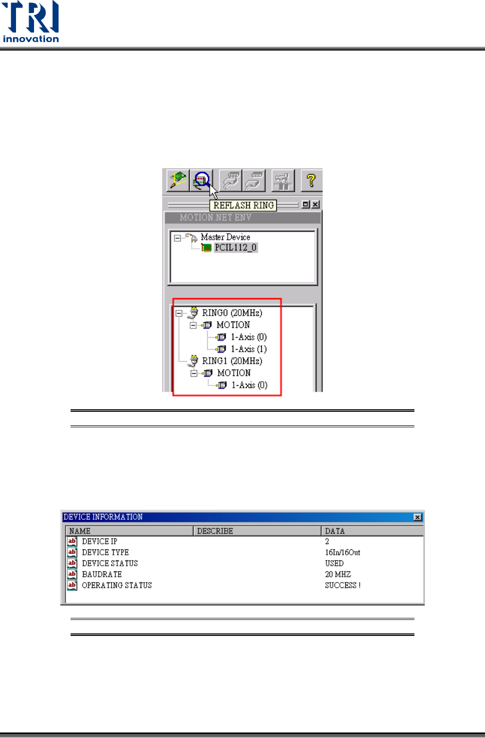
4) Connection Status for Expansion Devices
Once the system connection has been established and all devices have been identified, the
EzLink program will indicate the current connection and allocation status for all devices,
which can be seen in the device listing window as shown in the figure below.
If the axis numbers of Ring0 and Ring1 are reversed, check if the X and Y connectors on the
DSP card are properly connected.
Figure 114: EzLink Device List Screen
Clicking on a device from the device list will display its related information as shown in the
picture below.
The displayed information includes the IP number, device type, working status, connection
baud rate, and the operating status.
Figure 115: EzLink Device Information Screen
5) Connecting to the Extension Devices
Once the EzLink program finishes the scanning for Master devices, it will activate all the
master devices and attempt to establish connection to the associated extension devices. The
connection status is indicated at the bottom of the window. The changes during the
connection process are illustrated below.