00195398-0103-AI-01005Paket_DE_EN.pdf - 第49页
Asse mb ly In st ruct i on s 0100 5- Pac ket Edi t io n 12 /200 7 49 3.6. 4.1 Nozzle, t ype 90 5 ESD / 1 x 0. 15 [0305 7320-xx] Æ Cl ean the nozz les dail y to a void pickup a nd c entering e rrors. 3 Fig. 27 No zzl e, t…
Assembly Instructions 01005-Packet
Edition 12/2007
48
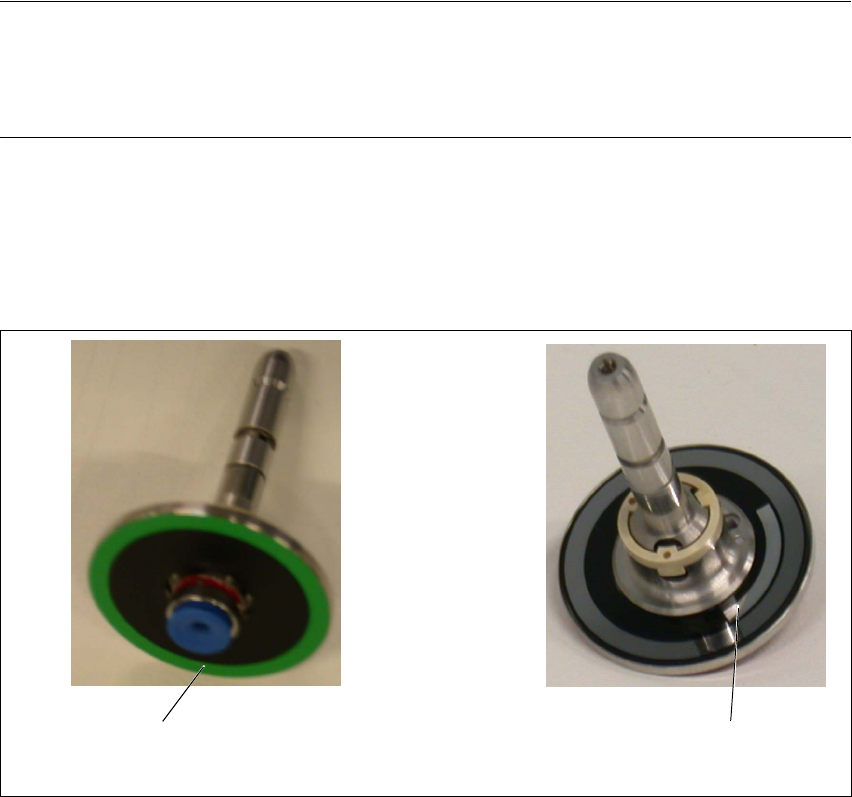
3.6.4 Inserting the Sleeve SP12 Comp. / 270 Degree Partition [03054107-xx]
The sleeves have a 270 degree partition and are designated with a green color ring. Each sleeve
can be identified by its unique serial number. 3
NOTE:
The sleeves must always be inserted into the same segment at the placement head in which they
were measured. Document this association (sleeve serial number with segment number) in the
machine log. 3
The "sleeve SP12 comp. / 270 degree partition" may only be used for the 01005 components with
the travel profiles 33/34 and 35. Otherwise the soft sleeve spring might cause the premature blow
off of the components. During the placement of larger component shapes, loss of placement
throughput may also occur. 3
Fig. 26 Sleeve SP12 comp. / 270 degree partition
Green color ring
270 degree partition
Assembly Instructions 01005-Packet
Edition 12/2007
49
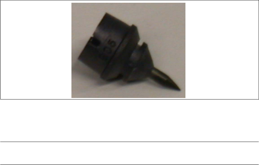
3.6.4.1 Nozzle, type 905 ESD / 1 x 0.15 [03057320-xx]
Æ Clean the nozzles daily to avoid pickup and centering errors.
3
Fig. 27 Nozzle, type 905 ESD / 1 x 0.15
3.6.5 Calibration of Changeover Table Height for SIPLACE D4
NOTE:
These settings only need to be performed for SIPLACE D4 machines. 3
3.6.5.1 Purpose
To measure the tape pockets of 01005 components, with the PCB camera, you need an optimum
focal position. This focal position is achieved by calibrating the height of the changeover table. A
correction height is determined for the changeover table at each location. 3
Depending on the height situation at a location, you will need to place small adjustment sheets
with a thickness of 0.5 and/or 1.0 mm between the changeover table support and the table itself.
These adjustment sheets are not specific to a particular changeover table and can remain at the
machine. 3
3.6.5.2 Determining the Changeover Table Height
To determine the required thickness of the adjustment sheet, move the Z-axis with the nozzle 901/
925 to the upper edge of the changeover table measuring gauge. The Z height is then read out
with the help of the CACCIA program. 3
Æ Attach "nozzle 901/925" to segment 1.
Æ In SITEST, start the function "Perform Head Reference Run". The Z-axis will be in the place-
ment position.
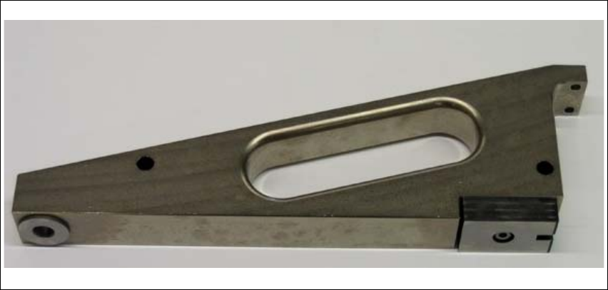
Æ Place the changeover table measuring gauge on track 1 of the changeover table.
Assembly Instructions 01005-Packet
Edition 12/2007
50
3
Fig. 28 Changeover table measuring gauge
Æ Move the gantry over the changeover table measuring gauge.
Æ Enable the Z-axis at the axis controller board.
Æ Take hold of the toothed belt and carefully push the Z-axis downwards, to the top of the gauge
(until you reach the nozzle).
Æ Read out the current position with CACCIA.
The actual position in digits can be read out online in the "Subsystem Control Center" at Z- RV
(gantry 1 or 4) with an active "query".