00195398-0103-AI-01005Paket_DE_EN.pdf - 第51页
Asse mb ly In st ruct i on s 0100 5- Pac ket Edi t io n 12 /200 7 51 3 Fig. 29 CACCIA Subsystem Co ntrol Center Æ Ca lculate the Z-di st anc e [ in m m ] according to t he fo llowing form ula: Zdistance[m m] = act ualpos…
Assembly Instructions 01005-Packet
Edition 12/2007
50
3
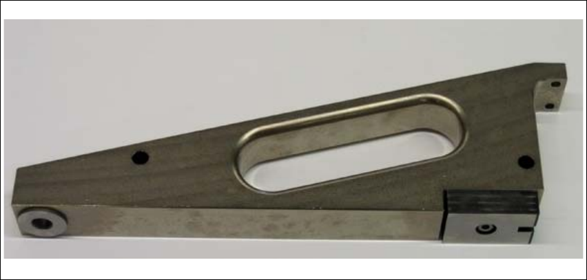
Fig. 28 Changeover table measuring gauge
Æ Move the gantry over the changeover table measuring gauge.
Æ Enable the Z-axis at the axis controller board.
Æ Take hold of the toothed belt and carefully push the Z-axis downwards, to the top of the gauge
(until you reach the nozzle).
Æ Read out the current position with CACCIA.
The actual position in digits can be read out online in the "Subsystem Control Center" at Z- RV
(gantry 1 or 4) with an active "query".
Assembly Instructions 01005-Packet
Edition 12/2007
51
3
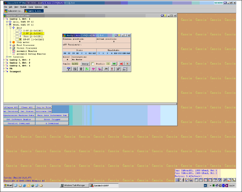
Fig. 29 CACCIA Subsystem Control Center
Æ Calculate the Z-distance [ in mm] according to the following formula:
Zdistance[mm] = actualpos[digit]* 0.0225 mm 3
Æ Place the changeover table measuring gauge on track 67 and repeat the height determination
process.

Assembly Instructions 01005-Packet
Edition 12/2007
52
3.6.5.3 Determining the Thickness of the Adjustment Sheets
The minimum Z-distance must not undershoot 7.2 (320 digits) after the adjustment sheets have
been fitted. Please note that not the medium value but the lowest Z-distance value for tracks 1 and
67 must not undershoot 7.2 mm. However, to ensure that the tape pocket is not too low, the lower
Z-distance should not undershoot 7.7 (342 digits). 3
Example:
Z-distance at changeover table measuring gauge on track 1 = 374 digits 3
Z-distance at changeover table measuring gauge on track 67 = 390 digits 3
Resulting Z-distance: 3
Zdistance= 374digits*0.0225mm = 8.415mm 3
Adjustment sheet thickness: 1mm 3
Z-distance after fitting adjustment sheet:7.415mm 3
3.6.5.4 Checking the Minimum Clearance
After raising the changeover table, you may experience a collision of the nozzle 905
(length 16.5 mm) with the feeder cover flap. To prevent this, determine the Z-distance at the top
edge of the feeder cover plate, before fitting the adjustment sheets. 3
Æ Check the minimum clearance between the nozzle 905 and the top edge of the feeder cover
plate.
Æ Determine the Z-distance as described at section 3.6.5 on page - 49, for the left, center and
right X positions of the head. In the Y direction, the gantry is pressed against the bumper during
measurement.
NOTE:
When using the nozzle 901/925, do not undershoot a Z-distance of 1.9 mm, taking into account
the height with adjustment sheet fitted. 3