00195398-0103-AI-01005Paket_DE_EN.pdf - 第52页
Asse mb ly In st ruct i on s 0100 5- Pac ket E di tio n 1 2 /20 07 52 3.6. 5.3 De termini ng the Thickness of the Adjustment S heet s The min imum Z-distance must not undershoot 7.2 (320 digits) af ter the adjustment she…
Assembly Instructions 01005-Packet
Edition 12/2007
51
3
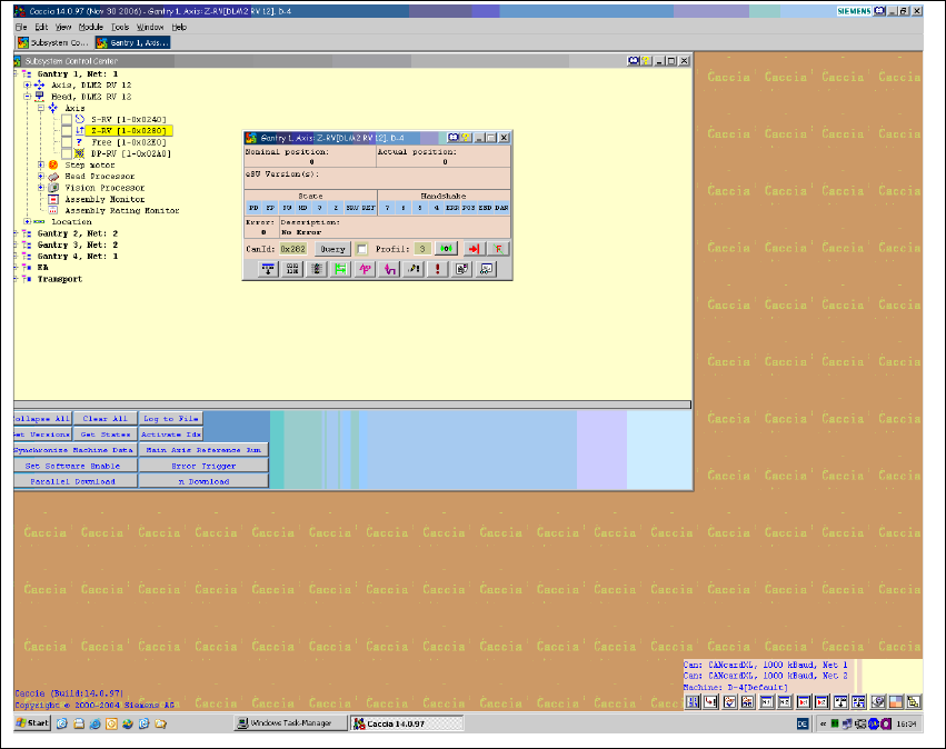
Fig. 29 CACCIA Subsystem Control Center
Æ Calculate the Z-distance [ in mm] according to the following formula:
Zdistance[mm] = actualpos[digit]* 0.0225 mm 3
Æ Place the changeover table measuring gauge on track 67 and repeat the height determination
process.

Assembly Instructions 01005-Packet
Edition 12/2007
52
3.6.5.3 Determining the Thickness of the Adjustment Sheets
The minimum Z-distance must not undershoot 7.2 (320 digits) after the adjustment sheets have
been fitted. Please note that not the medium value but the lowest Z-distance value for tracks 1 and
67 must not undershoot 7.2 mm. However, to ensure that the tape pocket is not too low, the lower
Z-distance should not undershoot 7.7 (342 digits). 3
Example:
Z-distance at changeover table measuring gauge on track 1 = 374 digits 3
Z-distance at changeover table measuring gauge on track 67 = 390 digits 3
Resulting Z-distance: 3
Zdistance= 374digits*0.0225mm = 8.415mm 3
Adjustment sheet thickness: 1mm 3
Z-distance after fitting adjustment sheet:7.415mm 3
3.6.5.4 Checking the Minimum Clearance
After raising the changeover table, you may experience a collision of the nozzle 905
(length 16.5 mm) with the feeder cover flap. To prevent this, determine the Z-distance at the top
edge of the feeder cover plate, before fitting the adjustment sheets. 3
Æ Check the minimum clearance between the nozzle 905 and the top edge of the feeder cover
plate.
Æ Determine the Z-distance as described at section 3.6.5 on page - 49, for the left, center and
right X positions of the head. In the Y direction, the gantry is pressed against the bumper during
measurement.
NOTE:
When using the nozzle 901/925, do not undershoot a Z-distance of 1.9 mm, taking into account
the height with adjustment sheet fitted. 3
Assembly Instructions 01005-Packet
Edition 12/2007
53
3.6.5.5 Fitting the Adjustment Sheet
3
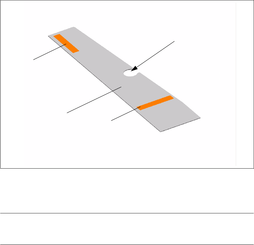
Fig. 30 Adjustment sheet
The adjustment sheets (1) have strips of adhesive tape (2) on both sides, so that they can be used
on both sides of the table contact surface. 3
NOTE:
Leave the cover sheet on the adhesive strips of the adjustment sheets until you have finished de-
termining the height. 3
Æ Remove the cover sheet from the adhesive strip (2) on the required side.
Æ Place the adjustment sheet (1) with the recess (3) over the ball calotte and attach the adjust-
ment sheet to the table contact surface.
Æ The adhesive strip which is still on the upper side of the adjustment sheet can be left there, as
the position of this cover sheet is outside the table contact surface.
2 3
1 3
2 3
3 3