00195398-0103-AI-01005Paket_DE_EN.pdf - 第60页
Asse mb ly In st ruct i on s 0100 5- Pac ket E di tio n 1 2 /20 07 60 3.7. 2 Contr olling a nd Configu ring the Com ponent S hape, if n ecessary In SIPLA CE P ro, the def ault com ponent shape s 9 6 and 97 are a lready d…
Assembly Instructions 01005-Packet
Edition 12/2007
59
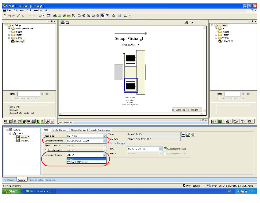
Fig. 35 SIPLACE Pro "setup editor" - "head" tab
Æ Go to "Component camera" and select the "RV Camera (38) 20x20" type.
Æ Ensure that the "Component sensor" is available at the machine.
Æ If the component sensor is not available, select "None" in the Setup Editor to deactivate the
component sensor.
Æ If the component sensor is available, you need to activate the sensor in this menu.
3
Assembly Instructions 01005-Packet
Edition 12/2007
60
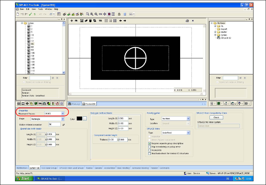
3.7.2 Controlling and Configuring the Component Shape, if necessary
In SIPLACE Pro, the default component shapes 96 and 97 are already defined for the 01005-com-
ponents. Check and, where necessary, configure the 01005 component settings. 3
Æ Open the Component Shape Editor in SIPLACE Pro.
Æ Open the component shape for a 01005-component (e.g. GF 96).
Æ Go to "Properties", choose the "Replacement Process" list field and select "01005".
Fig. 36 SIPLACE Pro "Component Shape Editor" - "CS" tab
After the component has been placed at the DLM3 placement head, the placement process
"01005" activates the validation of the component presence with specific checks. During this pro-
cess, SIPLACE Pro verifies automatically,
– whether the travel profile 33 or 34 for controlled placement and 35 for controlled pickup are
activated.
– whether "RV Camera (38) 20x20" is activated.
– whether the "Type 905" nozzle is activated.
– whether the feeder "3x8mm S-Tape 01005 CO" is activated.
– whether the vacuum check is activated.
– using the component camera, whether the component does no longer remain at the nozzle af-
ter placement. That means that the component has been placed safely.
Assembly Instructions 01005-Packet
Edition 12/2007
61
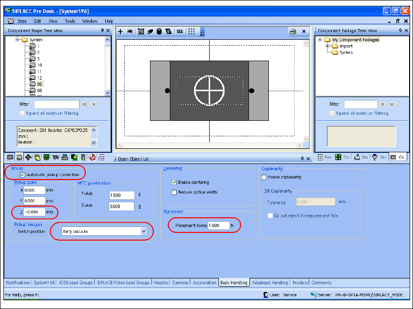
3.7.2.1 Configuring the Automatic Pickup Correction
Æ Select the "Basic handling" tab.
Æ Activate the checkbox "Automatic Pickup Correction".
Æ Check the default settings and make corrections, if necessary.
Æ Go to "Pickup Position" => "z" and enter the value -0,095 mm to adjust the head space height.
Æ Go to "Pickup vacuum => and select "Early vacuum".
Æ Enter a "Placement Force" of 1.0 N at "Placement".
Fig. 37 SIPLACE Pro "component shape editor" - "basic handling" tab