00195398-0103-AI-01005Paket_DE_EN.pdf - 第64页
Asse mb ly In st ruct i on s 0100 5- Pac ket E di tio n 1 2 /20 07 64 3. 7. 2. 4 Assi gn in g t he Ca me r a Æ S elect the "Cameras " t ab. Æ S elect from the list of t he available cam eras the "RV Camera…
Assembly Instructions 01005-Packet
Edition 12/2007
63
Æ Go to "Waiting time during pickup" and enter the value 10 ms (only for C&P 12 head).
NOTE:
If SIPLACE D1/D2/D4 is used together with the SIPLACE X-series, you need to create and main-
tain a second component shape for 01005 in conjunction with the C&P 20 head, where necessary.
In case the 01005-component is placed with the C&P 20 head, the "Waiting time during pickup"
option must be adjusted to the value 0 ms! 3
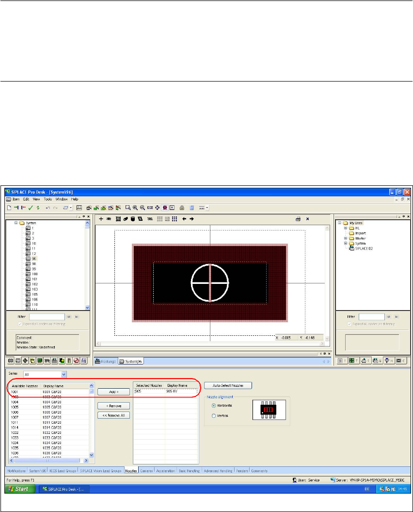
3.7.2.3 Assigning Nozzles
Æ Select the "Nozzles" tab.
Æ Select from the list of the available nozzles the "905" type and use the "Add >" button to add
this entry to the list auf the selected nozzles.
Fig. 39 SIPLACE Pro "component shape editor" - "nozzles" tab
Assembly Instructions 01005-Packet
Edition 12/2007
64
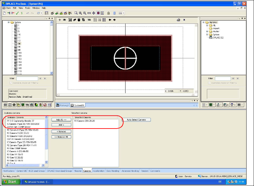
3.7.2.4 Assigning the Camera
Æ Select the "Cameras" tab.
Æ Select from the list of the available cameras the "RV Camera (38) 20x20" type and use the
"Hinzufügen >" button to add this entry to the list of the selected cameras.
Fig. 40 SIPLACE Pro "component shape editor" - "cameras" tab
Assembly Instructions 01005-Packet
Edition 12/2007
65
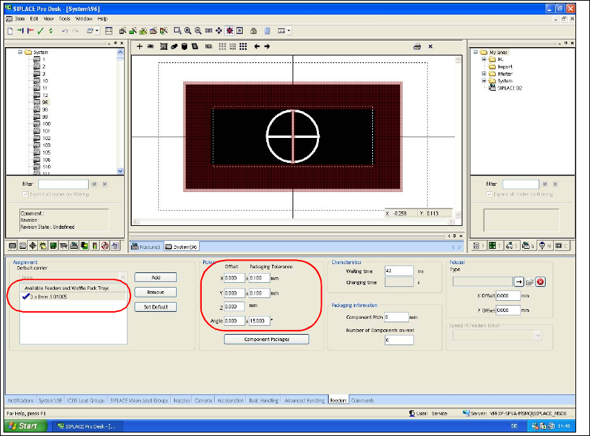
3.7.2.5 Assigning the Feeder
Æ Select the "Feeder" tab.
Æ Use the "Add" button to select the feeder type "3 x 8mm S 01005" from the feeder type list.
Æ Check the values for packing tolerance (+/- 0,1 mm) and angle (15°).
Fig. 41 SIPLACE Pro "component shape editor" - "feeder" tab