00195398-0103-AI-01005Paket_DE_EN.pdf - 第68页
Asse mb ly In st ruct i on s 0100 5- Pac ket E di tio n 1 2 /20 07 68 F ig. 44 Station s s oftw ar e " Co rr ect Pos it io n" Æ Use the cross-hai r t o c hec k t he component position. If necessary , correct t …
Assembly Instructions 01005-Packet
Edition 12/2007
67
3.9 Final Tasks and Verification
3.9.1 Verifiying the Calculated Pickup Position at the Station
Æ Stop the placement process.
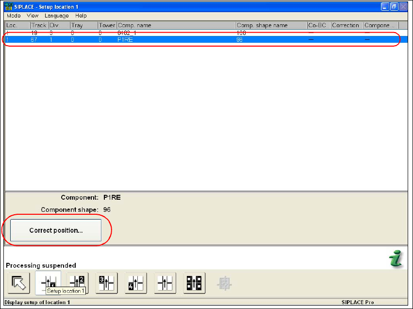
Æ Select the "Setup location" function in the main view of the stations software.
Æ Highlight in the list the feeder with the desired component.
Fig. 43 Stations software "Setup Location"
Æ Execute the "Correct position..." function.
Assembly Instructions 01005-Packet
Edition 12/2007
68
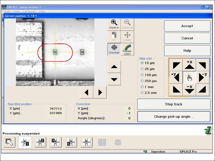
Fig. 44 Stations software "Correct Position"
Æ Use the cross-hair to check the component position. If necessary, correct the position with the
help of Teach.
Assembly Instructions 01005-Packet
Edition 12/2007
69
4 Appendix
4.1 Guideline for a Successful 1005-Placement
4.1.1 Summary of the most important Settings
4.1.1.1 on the SIPLACE Machine
– Enabling feeder position recognition
– Activating automatic compressed air switch off
4.1.1.2 SIPLACE Pro
Separate GF descriptions are used in SIPLACE Pro for capacitor and resistor. (Resistor: 96.gf and
capacitor: 97.gf) Both component shapes differ mainly in their component height. If reversed set
terminators are not allowed due to quality standards set by the customer, then face-down recog-
nition must be activated. Since face-down recognition is not permitted by the majority of the cus-
tomers, face-down recognition is viewed as standard setting for the following: 4
– Pickup (settings in SIPLACE PRO)
– activating face-down recognition for resistor
– non-contacting pickup with travel profile 35 - lower, no contact 01005
(in SIPLACE Pro Version 5.0)
– Travel Profile Raise: 2 - pickup, default
– Presence Check Pickup: activate
– Automatic Pickup Correction: activate
– enter Pickup Tolerances (packaging box) for the feeder either in the component shape de-
scription or component description! Recommended:(X=100µm / Y=100µm / angle=15°)
– Placement (settings in SIPLACE PRO)
– Travel Profile for Placement: 33 - downward, 01005 components
(in SIPLACE Pro Version 5.0)
– Travel Profile Raise: 9 - placement, default
– Placement Force: 1N
– Presence Check for Placement: no vacuum