00195398-0103-AI-01005Paket_DE_EN.pdf - 第69页
Asse mb ly In st ruct i on s 0100 5- Pac ket Edi t io n 12 /200 7 69 4 Appendix 4.1 Guideli ne fo r a Suc cess ful 1 005 -Placemen t 4.1. 1 Summar y of th e m ost im port an t S etting s 4. 1. 1. 1 on t h e SIPLACE M ach…
Assembly Instructions 01005-Packet
Edition 12/2007
68
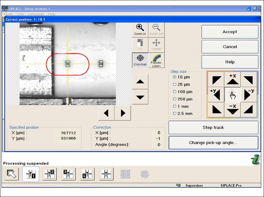
Fig. 44 Stations software "Correct Position"
Æ Use the cross-hair to check the component position. If necessary, correct the position with the
help of Teach.
Assembly Instructions 01005-Packet
Edition 12/2007
69
4 Appendix
4.1 Guideline for a Successful 1005-Placement
4.1.1 Summary of the most important Settings
4.1.1.1 on the SIPLACE Machine
– Enabling feeder position recognition
– Activating automatic compressed air switch off
4.1.1.2 SIPLACE Pro
Separate GF descriptions are used in SIPLACE Pro for capacitor and resistor. (Resistor: 96.gf and
capacitor: 97.gf) Both component shapes differ mainly in their component height. If reversed set
terminators are not allowed due to quality standards set by the customer, then face-down recog-
nition must be activated. Since face-down recognition is not permitted by the majority of the cus-
tomers, face-down recognition is viewed as standard setting for the following: 4
– Pickup (settings in SIPLACE PRO)
– activating face-down recognition for resistor
– non-contacting pickup with travel profile 35 - lower, no contact 01005
(in SIPLACE Pro Version 5.0)
– Travel Profile Raise: 2 - pickup, default
– Presence Check Pickup: activate
– Automatic Pickup Correction: activate
– enter Pickup Tolerances (packaging box) for the feeder either in the component shape de-
scription or component description! Recommended:(X=100µm / Y=100µm / angle=15°)
– Placement (settings in SIPLACE PRO)
– Travel Profile for Placement: 33 - downward, 01005 components
(in SIPLACE Pro Version 5.0)
– Travel Profile Raise: 9 - placement, default
– Placement Force: 1N
– Presence Check for Placement: no vacuum

Assembly Instructions 01005-Packet
Edition 12/2007
70
4.1.1.3 Handling of Nozzles
– Replace nozzles only with nozzle changer
– Avoid touching the nozzles tips to prevent pollution
– Always use an ultrasonic bath to clean nozzles (Mat.# 03042652-01)
Note:
The small deviation of the ceramic nozzle tip poses the risk of injury (comparable with a pin).4
4.1.1.4 PCB upport
The PCB must be supported in such a way that it is not resilient and cannot arch up or down. In
the case of extremely thin substrates, holohedral support, where necessary, with the help of vac-
uum tooling is recommended. Ceramic substrates may require ceramic substrate centering. 4
4.1.1.5 Testing First Placement Run
In order to verify whether all settings have been prepared and set correctly, a trial placement run
onto a PCB imprinted with soldering paste is recommended. A trial placement run onto adhesive
foil does not yield any meaningful results, since the soldering paste imprint has a significant impact
on the placement quality. 4