00195170-01 SA trailing cable.pdf - 第15页
Replacing the Trailing Cable Unit on X- Series M achines up to B-078 [03003199- xx] Service Manual Exchange of the trailing cable SIPLACE HF and X-Series 15 3 Replacing the T railing Cable Unit on X-Series Machines up to…
Replacing the Trailing Cable Unit [03039709-xx]
Conversion on SIPLACE HF Machines up to A 219
14 Service Manual Exchange of the trailing cable SIPLACE HF and X-Series
X Fit the pressure plate for the new trailing cable
unit onto the new cable supports, with the 4
M3x35 screws from the retrofitting set.
X If the pressure plate does not fit into the exi-
sting drillings on the gantry, loosen the pressu-
re plate clamp and adjust it.
X Tighten the clamp again and fit the pressure
plate onto the gantry drillings.

Replacing the Trailing Cable Unit on X-Series Machines up to B-078 [03003199-
xx]
Service Manual Exchange of the trailing cable SIPLACE HF and X-Series
15
3 Replacing the Trailing Cable Unit on X-Series
Machines up to B-078 [03003199-xx]
Parts
Digital trailing cable unit 1P [03015419-03]
Digital trailing cable unit 2P U [03002306-03]
Digital trailing cable unit 2P G [03003199-03]
Hose nippers for cutting the compressed air hoses
Pipe/hose cutters [00381443-01]
Hose unlocking device [03047090-xx]
Loctite 241 [02101037-01]
Preparation
The trailing cable unit is supplied as a complete assembly. Depending upon the configuration of the ma-
chine, you will need to remove the relevant modules, covers and cover plates before you can dismantle
the trailing cable.
X Where necessary, remove the cover plates
from the gantry trailing cable. Mark their exact
position to ensure correct replacement later.
X Remove the top central cover from the SIPLA-
CE machine.
X Remove the upright covers on the trailing ca-
ble interface, so that you can reach the trailing
cable.
Replacing the Trailing Cable Unit on X-Series Machines up to B-078 [03003199-xx]
Overview
16 Service Manual Exchange of the trailing cable SIPLACE HF and X-Series
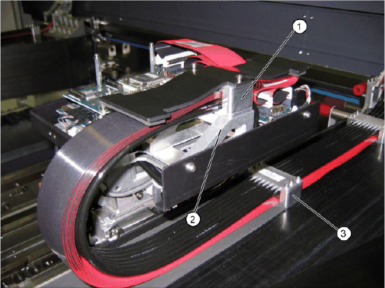
3.1 Overview
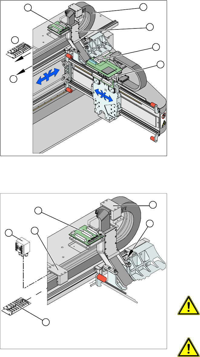
3.2 Disassembly
X The flat ribbon cable and the camera cable are
run from the head board (1) via the trailing ca-
ble console (2) and the power track chain (3)
to the gantry interface (7) and the trailing cable
interface (4) . The camera cable ends at the
hotlink card (8).
X The compressed air hoses are run from the
pneumatic distributor (6), via the trailing cable
console (2) and the power track chain(3) to the
gantry distributor (5) .
5
5
6
7
1
4
3
2
X Disconnect the flat ribbon cable and the came-
ra cable at the trailing cable interface (1) or the
hotlink card. Take care not to lose the brackets
for the plug-and-socket connections when you
open the flat ribbon cable. They could fall out
and be lost.
X Remove cable ties where necessary.
X Remove the cover on the gantry distributor (5).
X Loosen the screws fastening the gantry distri-
butor (5).
X Pull the compressed air hoses off the gantry
distributor (2) .
WARNING: Risk of injury to the
hands
X Use the hose unlocking device to
remove the hose [03047090-xx].
ATTENTION:
Observe the order in which the con-
nections are arranged. You will need
this sequence later, for reassembly
purposes.
3
3
4
5
1
2