00195170-01 SA trailing cable.pdf - 第18页
Replacing the Trailing Cable Unit on X-Series Machines up to B-078 [03003199-xx] Installation 18 Service Manual Exchange of the trai ling cable SIPLACE HF and X-Series 3.3 Inst allation X Loosen the 4 screws (1) fastenin…
Replacing the Trailing Cable Unit on X-Series Machines up to B-078 [03003199-
xx]
Service Manual Exchange of the trailing cable SIPLACE HF and X-Series
17
NOTE:
Connect the gantry distributor to the new trailing
cable and install it in the machine.
X Secure the end of the trailing cable (with cable
ties) in the machine to prevent it hanging loo-
sely and damaging other machine compon-
ents.
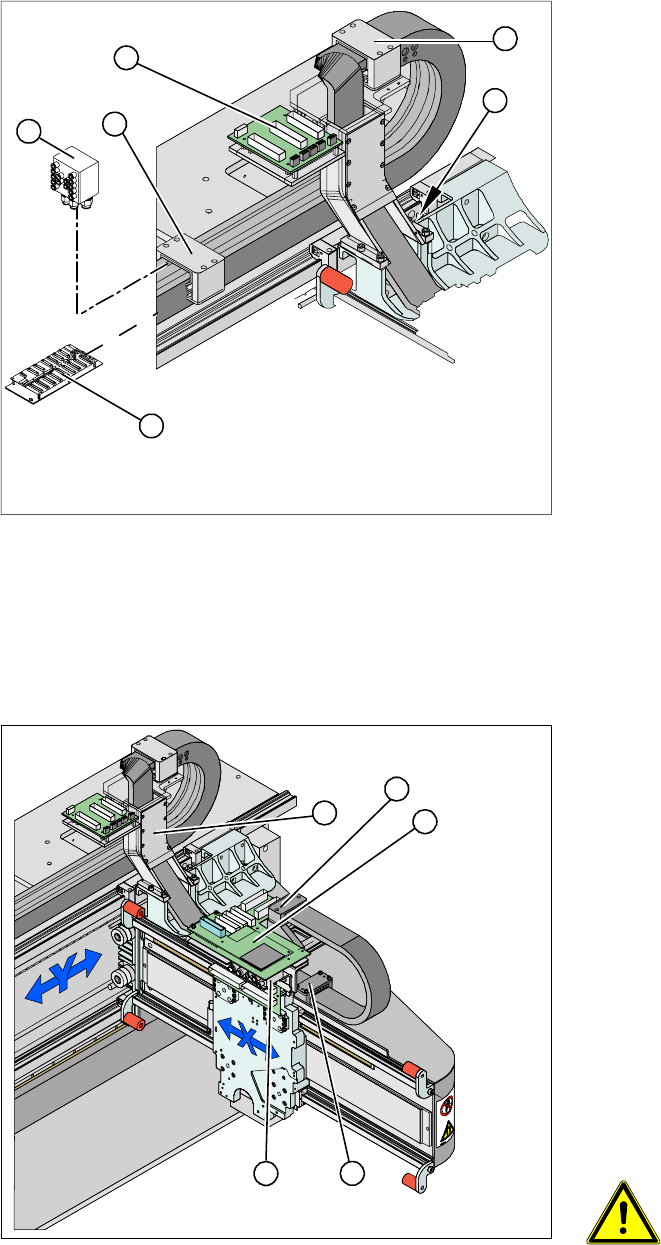
X Remove all necessary cable ties from the gan-
try interface (2) and unplug the flat ribbon ca-
ble.
X Disconnect the cables for the motor, proximity
switches, read head and temperature sensor
from the gantry interface (2) .
NOTE:
The gantry interface board is fitted onto the cable
holder of the new trailing cable unit.
X Pull the cooling tubes(4) for the Y motor off the
connection piece.
X Loosen the screws fastening the pressure pla-
tes (3). to the power track chain. These screws
have been secured with locking paint .
NOTE:
Only the fastening screws will be loosened. The
clamps for the flat ribbon cable remain in place.
3
3
4
5
1
2
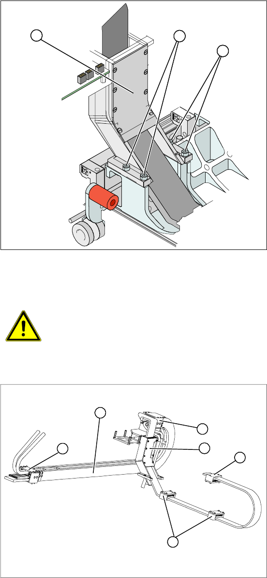
X Disconnect the flat ribbon cable from the head
board (1).
X Remove the pressure plate (3).
X Loosen the screws fastening the pressure pla-
te (3) to the head mount and the two screws on
the gantry (5).
NOTE:
X Only the fastening screws will be loosened.
The clamps for the flat ribbon cable remain in
place.
X Take care not to lose the contact discs and the
spacer bolts and also mark where they were
fitted. These will need to be correctly replaced
later.
X Disconnect the hoses from the pneumatic dis-
tributor (2).
WARNING: Risk of injury to the
hands
X Use the hose unlocking device to
remove the hose [03047090-xx].
5
5
1
4
3
2
Replacing the Trailing Cable Unit on X-Series Machines up to B-078 [03003199-xx]
Installation
18 Service Manual Exchange of the trailing cable SIPLACE HF and X-Series
3.3 Installation
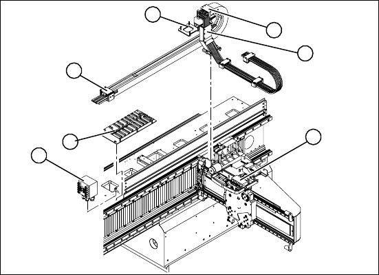
X Loosen the 4 screws (1) fastening the trailing
cable console (2) and carefully remove the
complete trailing cable unit from the machine.
NOTE:
The fastening screws are secured with Loctite.
1
1
2
CAUTION:
Handle the new trailing cable unit carefully and enlist the help of a second per-
son if necessary. Make sure that the flat ribbon cable and the compressed air
hoses are not rubbed against any parts or kinked. Look out for sharp edges.
1. Complete trailing cable unit
2. Pressure plates on the power track chain
3. Pressure plates on the gantry
4. Pressure plate on the head mount
5. Trailing cable console
X Carefully bring the new trailing cable (1) into
the correct position. Make sure you do not
twist it.
X Temporarily fasten the ends to the machine
frame (by tying them etc.).
2
5
1
4
3
2
Replacing the Trailing Cable Unit on X-Series Machines up to B-078 [03003199-
xx]
Service Manual Exchange of the trailing cable SIPLACE HF and X-Series
19
X Fit the gantry interface board onto the cable
holder (4) of the new trailing cable unit.
X Fasten the trailing cable console (1) loosely
with a screw.
X Clean the trailing cable contact surface on the
machine base with a dry cloth.
X Starting from the trailing cable console (1), run
the flat ribbon cable and hoses to the relevant
connections:
Pneumatic distributor (2)
Trailing cable interface (3)
Gantry interface (4)
Gantry distributor (5)
X Reconnect to the electrical system. Observe
the correct connector assignment.
X Shorten the compressed air hoses to the opti-
mum length, making sure that they are not too
short or long. They must engage firmly but
should not buckle.
X Reconnect to the compressed air supply. Ob-
serve the correct connector assignment.
X Fasten the pressure plates (6) loosely to the
machine base.
X Check that the power track chain can run alo-
ng the top of the machine base without ob-
struction. Move the Y-axis back and forth to
check this.
X Correct at the trailing cable console (1) and at
the pressure plates, where necessary.
X Fix the two pressure plates (6) and the trailing
cable console (1). Use Loctite 241 locking
paint.
X Tighten the trailing cable console (1) fastening
screws crosswise.
2
5
4
6
6
1
3