00195170-01 SA trailing cable.pdf - 第20页
Replacing the Trailing Cable Unit on X-Series Machines up to B-078 [03003199-xx] Installation 20 Service Manual Exchange of the trai ling cable SIPLACE HF and X-Series X Reconnect the Y motor cooling tubes to th e connec…
Replacing the Trailing Cable Unit on X-Series Machines up to B-078 [03003199-
xx]
Service Manual Exchange of the trailing cable SIPLACE HF and X-Series
19
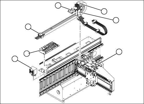
X Fit the gantry interface board onto the cable
holder (4) of the new trailing cable unit.
X Fasten the trailing cable console (1) loosely
with a screw.
X Clean the trailing cable contact surface on the
machine base with a dry cloth.
X Starting from the trailing cable console (1), run
the flat ribbon cable and hoses to the relevant
connections:
Pneumatic distributor (2)
Trailing cable interface (3)
Gantry interface (4)
Gantry distributor (5)
X Reconnect to the electrical system. Observe
the correct connector assignment.
X Shorten the compressed air hoses to the opti-
mum length, making sure that they are not too
short or long. They must engage firmly but
should not buckle.
X Reconnect to the compressed air supply. Ob-
serve the correct connector assignment.
X Fasten the pressure plates (6) loosely to the
machine base.
X Check that the power track chain can run alo-
ng the top of the machine base without ob-
struction. Move the Y-axis back and forth to
check this.
X Correct at the trailing cable console (1) and at
the pressure plates, where necessary.
X Fix the two pressure plates (6) and the trailing
cable console (1). Use Loctite 241 locking
paint.
X Tighten the trailing cable console (1) fastening
screws crosswise.
2
5
4
6
6
1
3
Replacing the Trailing Cable Unit on X-Series Machines up to B-078 [03003199-xx]
Installation
20 Service Manual Exchange of the trailing cable SIPLACE HF and X-Series
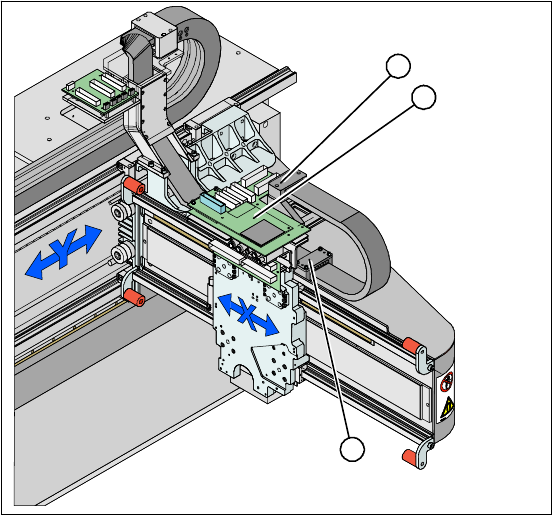
X Reconnect the Y motor cooling tubes to the
connection pieces.
X Install the 3 pressure plates (1) to the gantry
and the head mount (2).
X Fit the head board (3). Make sure you do not
lose the contact disks or spacer bolts.
X Plug in all connections/terminals. Observe the
correct connector assignment.
X Fasten new cable ties at the original points.
X Replace all cover plates.
5
1
3
2

Replacing the Trailing Cable Unit (IGUS) on X-Series Machines from B-079
[03021065-xx] onwards
Service Manual Exchange of the trailing cable SIPLACE HF and X-Series
21
4 Replacing the Trailing Cable Unit (IGUS) on X-
Series Machines from B-079 [03021065-xx]
onwards
See also:
J 4.2 Preparing the Trailing Cable Unit [J 22]
4.1 Introduction
Parts
Digital trailing cable unit 1P [03022236S01]
Digital trailing cable unit 2P U [03022237S01]
Digital trailing cable unit 2P G [03021065S01]
Hose nippers for cutting the compressed air hoses
Hose unlocking device [03047090-xx]
Pipe/hose cutters [00381443-01]
Vacuum pump retrofitting instructions, where necessary [00195089-01]:
Loctite 241 [02101037-01]
The following tools are provided with trailing cable units which have an "S" number:
Gauge fortrailing cable units for gantries 1+3 of X-series machines [00383029-01]
Gauge for trailing cable units for gantries 2+4 of X-series machines [00383057-01]
Edding marker pen, white [00382740-01]
QS-6 connection assembly [03049770-01]
Depending upon the configuration of the machine,
you will need to remove the relevant modules, co-
vers and cover plates before you can dismantle
the trailing cable.
X Where necessary, remove the cover plates
from the gantry trailing cable. Mark their exact
position to ensure correct replacement later.
X Remove the top central cover from the SIPLA-
CE machine.
X Remove the upright covers on the trailing ca-
ble interface, so that you can reach the trailing
cable.