00195170-01 SA trailing cable.pdf - 第30页
Replacing the Trailing Cable Unit (IGUS) on X- Series Machines from B-079 [03 021065-xx] onwards Installation 30 Service Manual Exchange of the trai ling cable SIPLACE HF and X-Series X Fasten the trailing cable console …
Replacing the Trailing Cable Unit (IGUS) on X-Series Machines from B-079
[03021065-xx] onwards
Service Manual Exchange of the trailing cable SIPLACE HF and X-Series
29
4.5 Installation
CAUTION:
Handle the new trailing cable unit ca-
refully and enlist the help of a second
person if necessary. Make sure that
the flat ribbon cable and the compres-
sed air hoses are not rubbed against
any parts or kinked. Look out for sharp
edges.
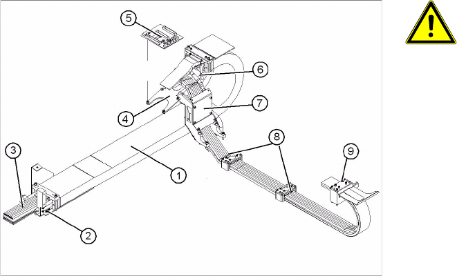
1. Complete trailing cable unit
2. Mounting block
3. Compressed air hoses (shortened to optimum
length with gauge)
4. Bracket for gantry interface
5. Gantry interface
6. Connection piece for cooling tubes to Y-axis
motor
7. Trailing cable console
8. Clamp on back of gantry
9. X trailing cable clamp
X Carefully bring the new trailing cable (1) into
the correct position. Make sure you do not
twist it.
X Temporarily fasten the ends to the machine
frame (by tying them etc.).
X Fit the gantry interface board (5) onto the hol-
der (4) of the new trailing cable.
Replacing the Trailing Cable Unit (IGUS) on X-Series Machines from B-079 [03021065-xx] onwards
Installation
30 Service Manual Exchange of the trailing cable SIPLACE HF and X-Series
X Fasten the trailing cable console (7) loosely
with a screw.
X Clean the trailing cable contact surface on the
machine base with a dry cloth.
X Starting from the trailing cable console (7), run
all cables and hoses to the relevant connec-
tions:
X Reconnect the head board to the electrical sy-
stem . Observe the correct connector assign-
ment.
X Reconnect the pneumatic distributor to the
compressed air supply. Observe the correct
connector assignment.
X The compressed air hoses need to be shor-
tened to the correct length with the help of the
gauge. See also Section 4.2 Preparing the
Trailing Cable Unit [J 22]They must engage
firmly but should not buckle.
X Screw the clamps (8) and (9) loosely into pla-
ce.
X Check that the power track chain can run alo-
ng the top of the machine base without ob-
struction. Move the Y-axis back and forth to
check this.
X Correct, if necessary, at the trailing cable con-
sole (7) and at the clamps (8) and (9).
X Fix the two clamps (8) and (9) and the trailing
cable console into place (7). Use Loctite 241
locking paint.
X Tighten the trailing cable console (7) fastening
screws crosswise.
X Install the trailing cable mounting block (2) to
the machine base.
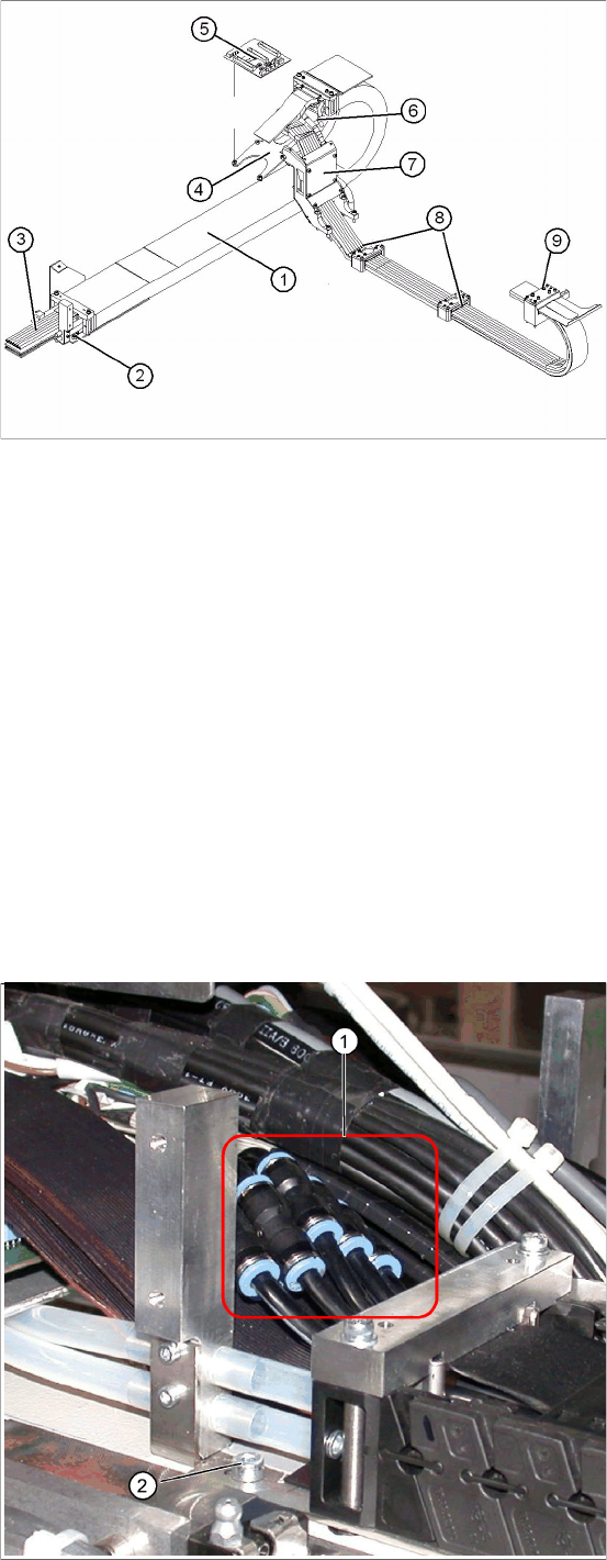
Connect the compressed air hoses to the
pneumatic distributor in the machine base
The compressed air hoses are run to the pneuma-
tic distributor in the machine base. The compres-
sed air hoses which are run inside the machine,
need to be cut and then connected with the cable
ties (03049770-01) to the trailing cable unit, at the
correct position (1).
X Place the gauge against the edge of the moun-
ting block and mark the trailing cable compres-
sed air hoses. See also: Section 4.2 Preparing
the Trailing Cable Unit [J 22].
Replacing the Trailing Cable Unit (IGUS) on X-Series Machines from B-079
[03021065-xx] onwards
Service Manual Exchange of the trailing cable SIPLACE HF and X-Series
31
See also:
J 1.3 Handling the Hose Unlocking Device [03047090-xx] [J 6]
CAUTION: Shortening and connecting the compressed air hoses
X Mark the order in which the compressed air hoses are arranged (from 1 to 7
– from inside to outside). This ensures that you connect the correct hoses to
one another again afterwards.
X Make sure that the correct gauge is used (for the appropriate gantries) and
that the hoses are not cut too short.
X Make sure that the cable ties are not positioned above one another. Use the
gauge to cut the individual hoses to the correct lengths.
X Shorten the compressed air hoses for the new
trailing cable at the points marked.
X The 7 hoses for the new trailing cable are con-
nected to one another. Carefully separate the-
se from one another as far as the mounting
block.
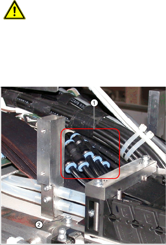
X Connect the trailing cable compressed air ho-
ses with the cable ties (1). Observe the mar-
kings (1-7 from inside to outside).
X Reconnect the Y motor cooling tubes to the
connection pieces.
X If you are using the optional "vacuum pump",
reconnect the compressed air hoses.
X Fasten new cable ties at the original points.
X Replace all cover plates.