00198654-01_UM_Nozzle_Cleaning_Station_EN - 第15页
2 Operational safety 2.3 Safety instructions for operation User Manual SIPLACE Nozzle Cleaning Station 09/2019 15 2.3 Safety instructions for operation 2.3.1 Safety instructions for closing the protective covers The prot…
2 Operational safety
2.2 Warning labels
14 User Manual SIPLACE Nozzle Cleaning Station 09/2019
2.2 Warning labels
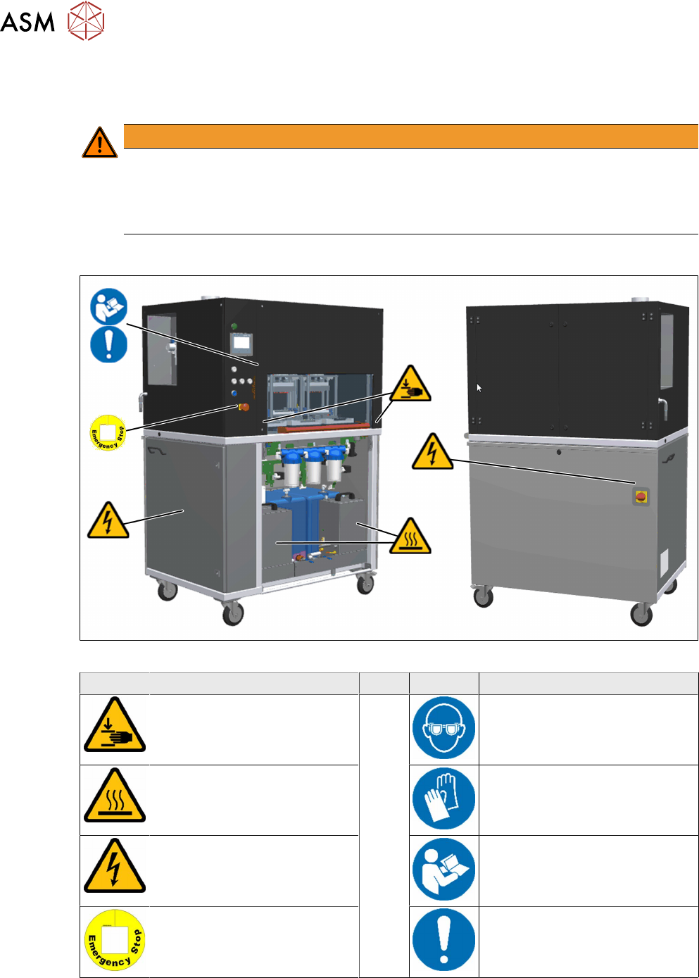
The following diagrams show the position of the warning labels at the nozzle cleaning station.
WARNING
Damage to warning labels!
The warning labels can be damaged or destroyed by abrasive cleaning agents or solvents.
► The warning labels can be damaged by abrasive cleaning agents or solvents.
► Replace any damaged or illegible warning labels.
2.2.1 Meaning and description of warning labels
Fig.3: Warning labels in the nozzle cleaning station
Symbol Description Symbol Description
Hand crushing hazard Wear eye protection
Hot surface Wear safety gloves
High voltage: electrical equip-
ment
Read the Operating Instructions
before starting this machine
Warning label on the EMER-
GENCY STOP button
Operation by trained and author-
ized personnel only
2 Operational safety
2.3 Safety instructions for operation
User Manual SIPLACE Nozzle Cleaning Station 09/2019 15
2.3 Safety instructions for operation
2.3.1 Safety instructions for closing the protective covers
The protection cover can be opened upwards. To avoid risk of injury when closing the protective
covers on the nozzle cleaning station, the operator must instruct the personnel concerned to al-
ways follow the instructions below when handling the protective covers.
CAUTION
Risk of crushing hands!
Risk of crushing hands if the protective covers are not closed correctly.
► Close the protective covers in accordance with the following instructions.
► To open or close the protective cover, always take hold it by the grab handle.
► When closing, do not reach into the gap between the protective cover and panel.
► When closing the protective cover, make sure that the area in which it is moved is free
of obstruction and that no other people are at risk of injury.
2.4 Safety features
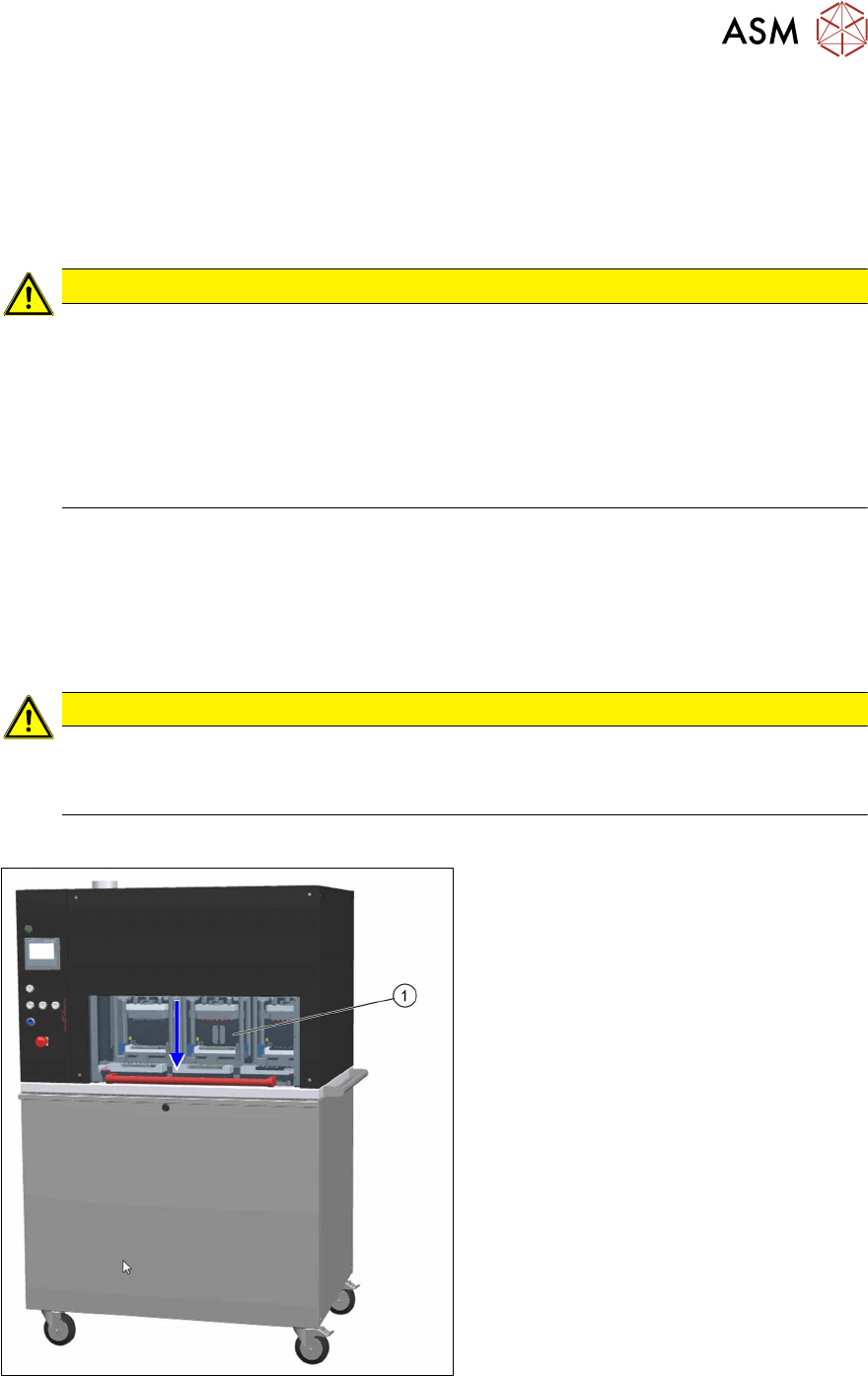
2.4.1 Protective cover
The travel range of the shaft cleaning modules is covered with a movable protective cover to pre-
vent unauthorized access to the inside of the nozzle cleaning station.
CAUTION
Risk of damage!
The protective cover could be damaged if too much force is exerted.
► Only move it up and down without pressing or pulling.
Function
Fig.4: NCS - protective cover
If the protective cover(1) is opened upward,
the power supply to the shaft cleaning mod-
ules will be immediately interrupted. The
cleaning modules stop working and the mes-
sage "cover open” is displayed on the
screen.
Close the protective cover and press the
START button (see 2.4.2 "Switches and but-
tons" [}16]), to continue cleaning.
2 Operational safety
2.4 Safety features
16 User Manual SIPLACE Nozzle Cleaning Station 09/2019
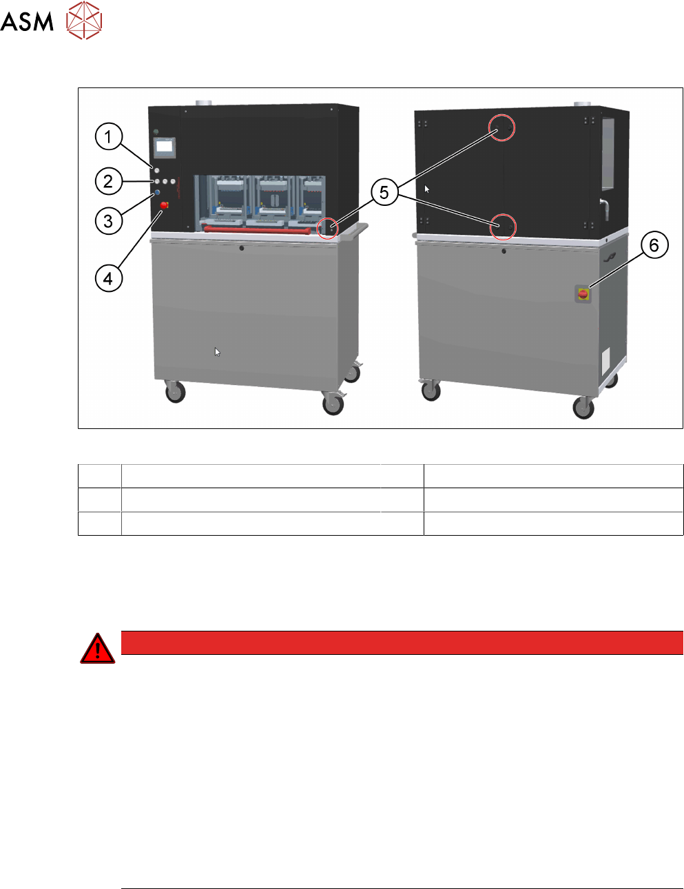
2.4.2 Switches and buttons
Fig.5: NCS - position of switches and buttons
1 Start / stop button for shaft cleaning 2 Start / stop button for tip
3 Reset button 4 Emergency stop button
5 Position switches 6 Main switch
2.4.2.1 Switches and buttons - description of functions
Main switch in OFF position
The main power switch disconnects the phase L1 from the power supply.
DANGER
Dangerous voltage levels!
The machine is supplied with 1 x 220 V~ ± 10 %, 50/60 Hz or optionally with 1 x 110 V~ ±
10 %; 50/60 Hz mains voltage. This means that some parts of the system carry potentially
lethal voltages - even when switched off at the main power switch.
Incorrect handling of the nozzle cleaning station can therefore result in death or severe in-
jury or considerable damage to equipment.
The following components still carry potentially lethal voltages even if the main power
switch is switched off:
► Always follow the applicable accident prevention and DIN regulations (particularly EN
60204, part 1 or IEC 60204, part 1) and the applicable regulations in your own coun-
try.
► The safety door to the power supply must ONLY be opened by appropriately qualified
and trained personnel.
Main switch in ON position
When the main switch is switched to ON, the mains voltage is switched through and all AC/DC con-
verters are addressed. The control computer starts and all supply voltages are made available in-
ternally.