00198654-01_UM_Nozzle_Cleaning_Station_EN - 第38页
4 Setting up and commissioning 4.3 Infrastructure at the installation location 38 User Manual SIPLACE Nozzle Cleaning Station 09/2019 4.3 Infrastructure at the installation location The floor on which the nozzle cleaning…
4 Setting up and commissioning
4.2 Configuration when delivered
User Manual SIPLACE Nozzle Cleaning Station 09/2019 37
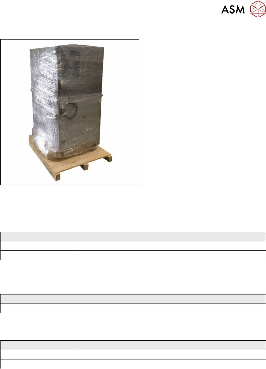
4.2.5 Transporting the placement machine in the shipping crate or on the pallet
Fig.19: Transportation crate/pallet - attachment points for
transportation with the fork-lift
The transport crate or pallet should only be
lifted at the side.
► Transport the SIPLACE NCS on the
pallet / the crate as near as possible to
the final site of use.
4.2.5.1 Shipping packaging dimensions
The dimensions of the pallets and wooden crates are listed in the following table:
Machine (L x W x H)
Pallet 1410 mm x 1210 mm
Wooden crate 1500 mm x 1300 mm x 2200
4.2.5.2 Weight of machine when ready for dispatch
The following table contains the weights of the placement machines prepared for dispatch, includ-
ing packaging.
Machine Dispatch
SIPLACE NCS 350 kg
4.2.5.3 Transportation equipment for transporting the placement machine in the packaging
Use a pallet truck / fork-lift truck with the following specification to carry the placement machine:
Machine Dispatch
Fork length Min. 1200 mm
Lifting power Min. 500 kg
4 Setting up and commissioning
4.3 Infrastructure at the installation location
38 User Manual SIPLACE Nozzle Cleaning Station 09/2019
4.3 Infrastructure at the installation location
The floor on which the nozzle cleaning station is installed must be firm and level, as a tilt could af-
fect the tightness of the system when the nozzle cleaning station is operated. The following are
suitable provided that the floor loading parameters, etc., are not exceeded:
●
Reinforced concrete ceiling constructions, e.g. ceilings in production halls
●
Reinforced concrete floor slabs, e.g. concrete floors in production halls without a basement
●
Rooms with double floors, provided that a stable foundation is included in the space between
them. The same setup conditions apply to this intermediate foundation, which can be made
from steel girders or concrete.
4.3.1 Ground levelness
The floor underneath the nozzle cleaning station may not exceed an incline of 0.63%. This corres-
ponds to an incline of 5 mm over a distance of 800 mm.
4.3.2 Machine weight and floor surface load
The machine weight and floor surface load can be found in section 3.3.1 "Technical data - dimen-
sions and weight" [}28].
4.3.3 Compressed air supply
4.3.3.1 Checking the compressed air supply
Check whether the compressed air supply complies with the prescribed placement machine spe-
cifications (see table in section 3.2.2 "Environmental conditions for operation" [}27]).
Record the compressed air characteristics at the installation location.
WARNING
Risk of injuries!
Risk of injuries from pressurized compressed air lines.
NEVER detach compressed air lines while they are still pressurized.
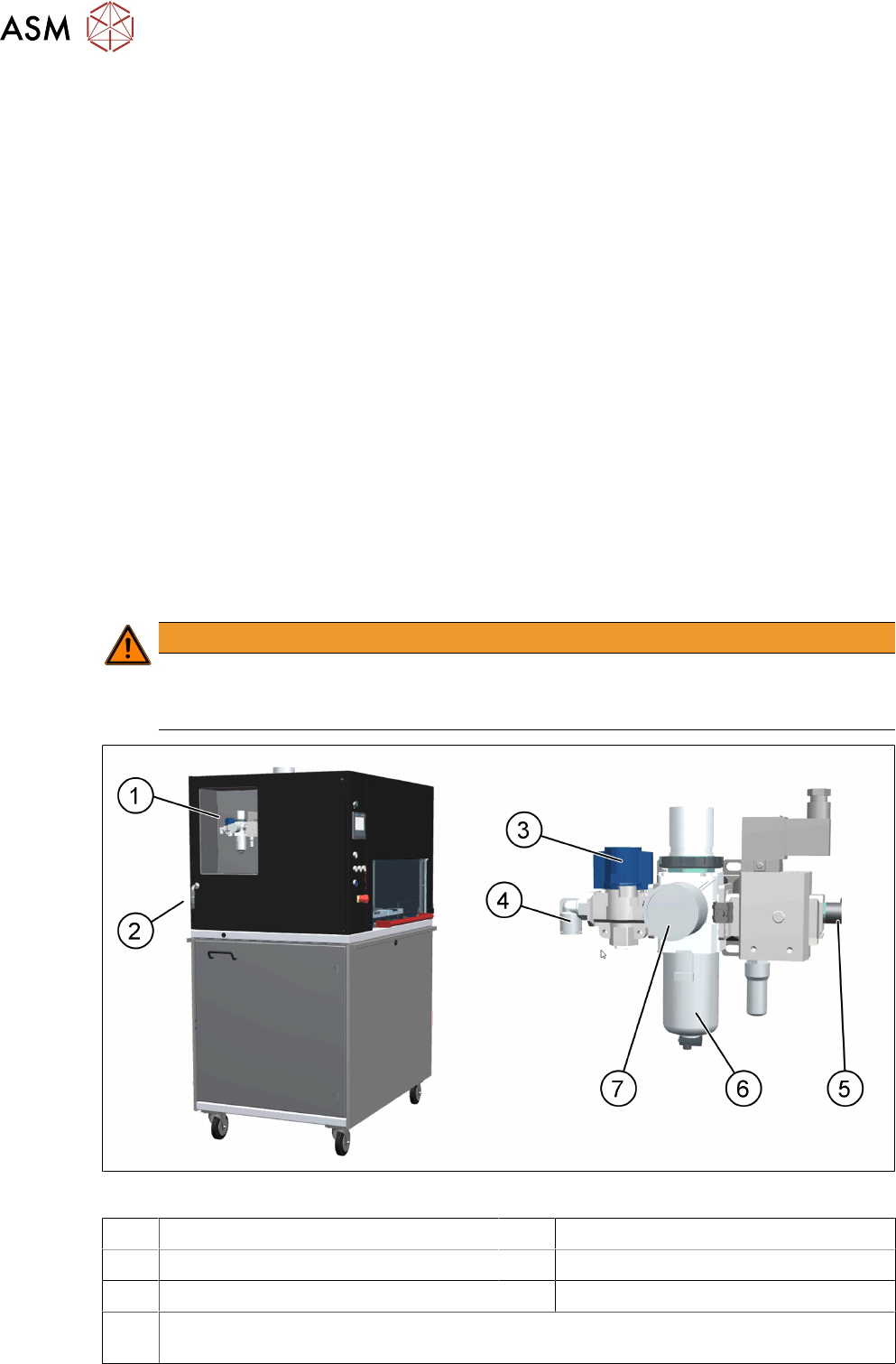
Fig.20: NCS - compressed air unit
1 Location of the compressed air unit 2 Compressed air connection
3 Stop valve in the "CLOSED" position 4 Compressed air supply
5 Compressed air supply for cleaning 6 Compressed air filter
7 Manometer for the nozzle cleaning station supply pressure
Target pressure: 0.50 ± 0.01MPa, 5.0 ± 0.1bar (display range 0–1.0MPa, 0–10bar)
4 Setting up and commissioning
4.4 Main power supply
User Manual SIPLACE Nozzle Cleaning Station 09/2019 39
4.4 Main power supply
DANGER
Dangerous voltage levels!
The machine is supplied with 1 x 220 V~ ± 10 %, 50/60 Hz or optionally with 1 x 110 V~ ±
10%; 50/60 Hz mains voltage. This means that some parts of the system carry potentially
lethal voltages - even when switched off at the main power switch.
Incorrect handling of the nozzle cleaning station can therefore result in death or severe in-
jury or considerable damage to equipment.
The following components still carry potentially lethal voltages even if the main power
switch is switched off:
► Always follow the applicable accident prevention and DIN regulations (particularly
EN60204, part 1 or IEC 60204, part 1) and the applicable regulations in your own
country.
► The safety door to the power supply must ONLY be opened by appropriately qualified
and trained personnel.
4.4.1 Checking the main power supply
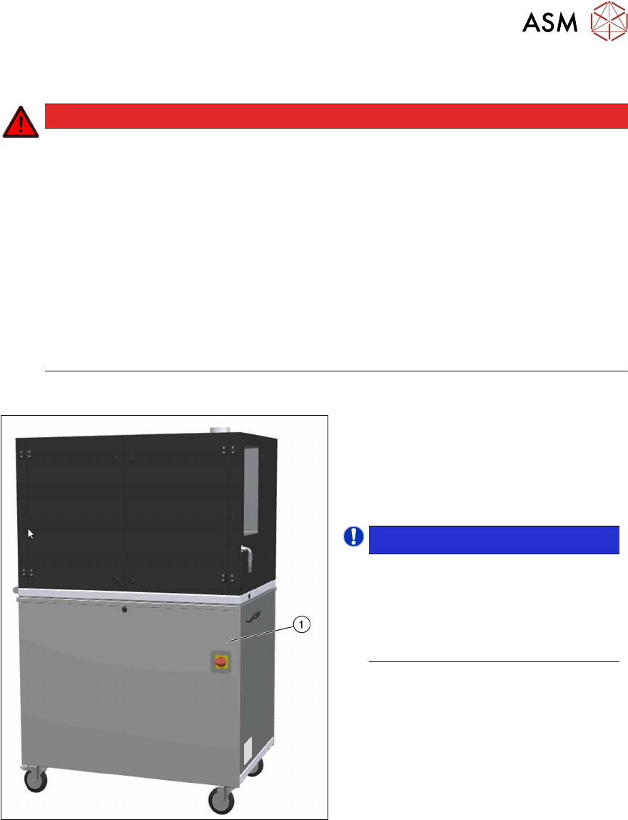
Fig.21: NCS - main power supply
Check whether the main power supply(1)
complies with the prescribed machine spe-
cifications (see table in section 3.2.3 "Com-
pressed air supply and compressed air spe-
cification" [}27]).
NOTICE!
Load peaks in power supply
For technical reasons, load peaks
occur in the power supply.
Please contact your power company to
clarify the mains impedance, if neces-
sary
.