00198654-01_UM_Nozzle_Cleaning_Station_EN - 第42页
4 Setting up and commissioning 4.5 Setting up the nozzle cleaning station 42 User Manual SIPLACE Nozzle Cleaning Station 09/2019 4.5.1 Fitting the cleaning modules The nozzle cleaning station is delivered without the cle…
4 Setting up and commissioning
4.5 Setting up the nozzle cleaning station
User Manual SIPLACE Nozzle Cleaning Station 09/2019 41
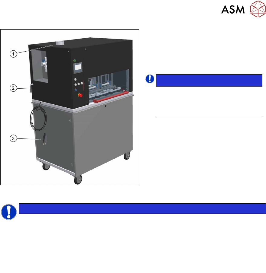
Fig.24: NCS - main connections
► Connect the NCS(1) to your local duct
system (tube Ø100mm).
► Connect compressed air supply(2).
► Connect power supply(3).
NOTICE!
Protective earth (PE)
Connect the protective earth (PE) line
according to applicable local regula-
tions.
.
NOTICE
Standard "E" type socket
The electrical connection of the device is adapted to the standard "E" type sockets. If you
need to use a different standard, replace the supplied plug with a suitable replacement.
DESIGNATION → POTENTIAL
1 → L
2 → N
YELLOW-GREEN → PE
4 Setting up and commissioning
4.5 Setting up the nozzle cleaning station
42 User Manual SIPLACE Nozzle Cleaning Station 09/2019
4.5.1 Fitting the cleaning modules
The nozzle cleaning station is delivered without the cleaning options installed. To fit the tip and
shaft cleaning modules proceed as follows.
4.5.1.1 Fitting the shaft cleaning module
The assembly of the shaft cleaning modules has to be done from the back of the NCS and requires
no additional tools.
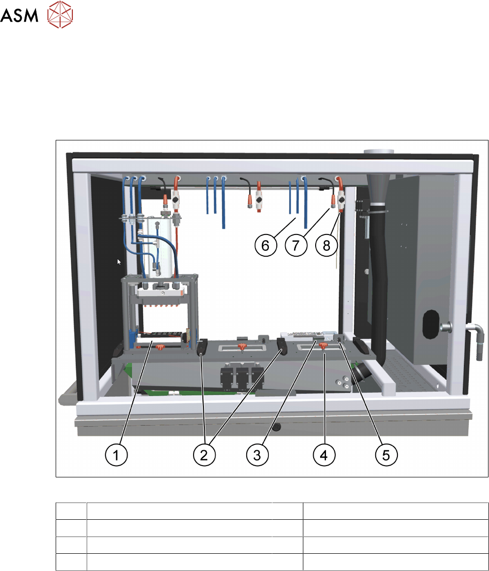
Fig.25: NCS - shaft cleaning cell
1 Shaft cleaning module 2 Guide rails
3 Stop pin 4 Fixing screw
5 Sensor for module recognition 6 Pneumatic supplies
7 Electrical connection to the sensor 8 Supply of the cleaning solution
4 Setting up and commissioning
4.5 Setting up the nozzle cleaning station
User Manual SIPLACE Nozzle Cleaning Station 09/2019 43
Fig.26: Inserting the shaft cleaning module
► Open the doors at the back of the NCS.
► Remove the black cover plate where
the module is to be installed.
► Insert the shaft cleaning module slightly
angled while placing the fitting pins
onto the black plastic support at the left
and right.
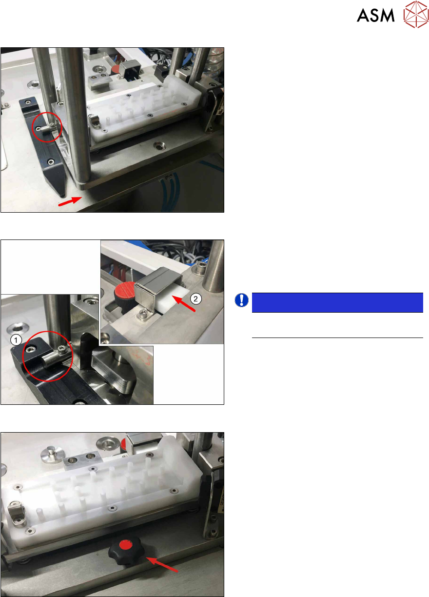
Fig.27: Hollow and end switch
► Move the module to the front until the
fitting pins sit in the hollow(1) and the
actuator operates the end switch(2).
NOTICE!
Ensure the proper seating of the seal-
ing below.
.
Fig.28: Positioning the module
► Fix the module in position using the
screw removed with the black cover
plate.