00198654-01_UM_Nozzle_Cleaning_Station_EN - 第63页
8 Maintenance 8.2 Changing a tip cleaning module User Manual SIPLACE Nozzle Cleaning Station 09/2019 63 8.2 Changing a tip cleaning module DANGER Risk of damage / life! Before changing the cleaning modules, stop the mach…
8 Maintenance
8.1 Maintenance types and scope
62 User Manual SIPLACE Nozzle Cleaning Station 09/2019
8.1.3 Periodic visual inspection
NOTICE
Loss of warranty!
The technical inspection is to be performed every 6 month. Failure to complete the tech-
nical inspection of the parts listed in the table below leads to the loss of warranty!
DANGER
Risk of damage / life!
Before maintaining the machine, disconnect it from the power supply with the main power
switch.
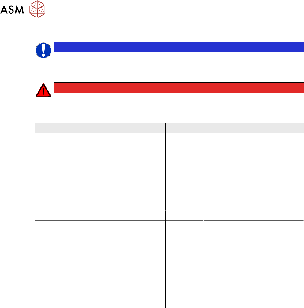
Pos. Inspected component/part Pcs. Intervals Guidelines
1 Pistons 44 6 months Visually inspect the tips (for mech-
anical damage). If in good health,
they are reusable.
2 Seals, membranes and other
wearing parts of the fluid
pumps
- 6 months Visually inspect the pump (for
mechanical damage and leaks). If
in good health, they are reusable.
3 Process cell seals - 6 months Visually inspect the baths, heads
and pistons (for mechanical dam-
age and leaks). If in good health,
they are reusable.
4 Piston outer seals 44 12 months Replace, irrespective of health.
5 Pneumatic actuators 19 12 months Inspect the clearances and seal
health. If in good health, they are
reusable.
6 Bath temperature sensors
(see the electrical system dia-
gram)
6 24 months Replace, irrespective of health.
7 Ball valves, solenoid valves,
and dampers (see the elec-
trical system diagram)
- 24 months If in good health, they are reusable.
8 Flexible air lines (see the parts
list)
- 24 months Replace, irrespective of health.
8 Maintenance
8.2 Changing a tip cleaning module
User Manual SIPLACE Nozzle Cleaning Station 09/2019 63
8.2 Changing a tip cleaning module
DANGER
Risk of damage / life!
Before changing the cleaning modules, stop the machine operation and disconnect it from
the power supply with the main power switch.
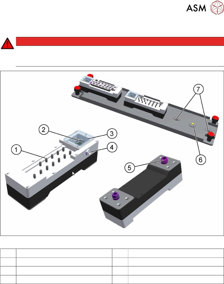
Fig.51: NCS - tip cleaning module
1 Seat sleeve 2 Overflow head
3 Inspection window 4 Fluid feeding pipe connection
5 O-ring for draining sealing 6 Presence switch
7 Drain holes in base plate
Performing the exchange
► Open the safety cover.
► If necessary, remove an existing magazine and put it aside on a safe place.
► Disconnect the fluid feeding pipe(4).
► Grab the tip cleaning module firmly with both hands and pull it up vertically.
► Put the module aside on a safe place and take a new one.
► Check the condition of the overflow sealing and the o-ring. In case of wear or visible damage
replace it with a new one.
► Wet the O-ring slightly before placing the tip cleaning module onto the base plate with the pipe
connection pointing to the back.
► Press the module into the plate with both hands.

8 Maintenance
8.2 Changing a tip cleaning module
64 User Manual SIPLACE Nozzle Cleaning Station 09/2019
► Attach the fluid feeding pipe.
► Check the levelling of the tip cleaning base plate– if required adjust it using the screws.
► Check the baths overflow level (see chapter 8.2.1 "Checking and adjustment the bath overflow
level" [}64]).
► Close the access door.
8.2.1 Checking and adjustment the bath overflow level
A successful nozzle tip cleaning process requires the nozzle tip to dip into the cleaning agent
without overflowing the liquid. Therefor the seat sleeves (see 8.2 "Changing a tip cleaning mod-
ule" [}63]) should be filled up just below the upper edge (~1mm).
To check the bath overflow level please proceed as follows:
► Start the device in the manual mode (password required).
► Select the tip cleaning module to be adjusted.
► Select the cleaning module.
► Start the pump until either the required maximal fluid level is exceeded (the liquid should stay
within the sleeves) or the overflow level is reached.
► If the overflow level has been reached and the maximal fluid level is within the range the out-
flow is adjusted well. If not the overflow level needs to be adjusted.
► Open the drain valve to drain the module.
► If the overflow level is not reached or the maximal fluid level is not the range the overflow level
needs to be adjusted.
► In case of not reaching the overflow level at exceeded maximal fluid level or reaching the
overflow level below the recommended fluid level the level height adjustment is necessary. In
order to do so disassemble the inspection window (gasket state assessment) of the cell and:
– If the maximal fluid level has been exceeded you should slowly screw the overflow head in
until the fluid surface in the sleeves drops to the required level (~1mm/rev.).
– If the fluid level has been set below the required level the overflow head should be un-
screwed to the fluid recommended level (~1mm/rev.);