WPC4 services manual - 第13页
Replacing Spare Parts Safety Instructions Service Manual SIPLACE WPC4 13 3 Replacing S p are Part s 3.1 Safety Instructions Preparations for service work X Finish all placement operations at the SIPLACE mach ine. X Switc…
Operational Safety
Safety Instructions Safety Instructions for Working with Strong Magnetic Fields
12 Service Manual SIPLACE WPC4

Replacing Spare Parts
Safety Instructions
Service Manual SIPLACE WPC4
13
3 Replacing Spare Parts
3.1 Safety Instructions
Preparations for service work
X Finish all placement operations at the SIPLACE machine.
X Switch the WPC4 off at the main switch.
X Carefully move the WPC4 out of the SIPLACE machine.
X Disconnect the WPC4 from the power supply.
WARNING: Nonobservance increases the risk of injury and/or damage to the machine!
The service work described in this manual may only be performed by specially trained service
technicians, with the appropriate additional qualifications and skills.
X Observe the safety instructions for the SIPLACE D1/D2, during all service work.
ATTENTION: Never open screws which have been sealed with locking varnish.
If screws sealed with locking varnish are opened, the assembly concerned will require extensive
readjustment.
X Only loosen screws sealed with locking varnish if the instructions in this manual explicitly ask
you to do so.
X If you open screws sealed with locking varnish without express instructions to do so, the
WPC4 must be taken to Siemens AG for readjustment.
Replacing Spare Parts
Overview of Main Assemblies
14 Service Manual SIPLACE WPC4
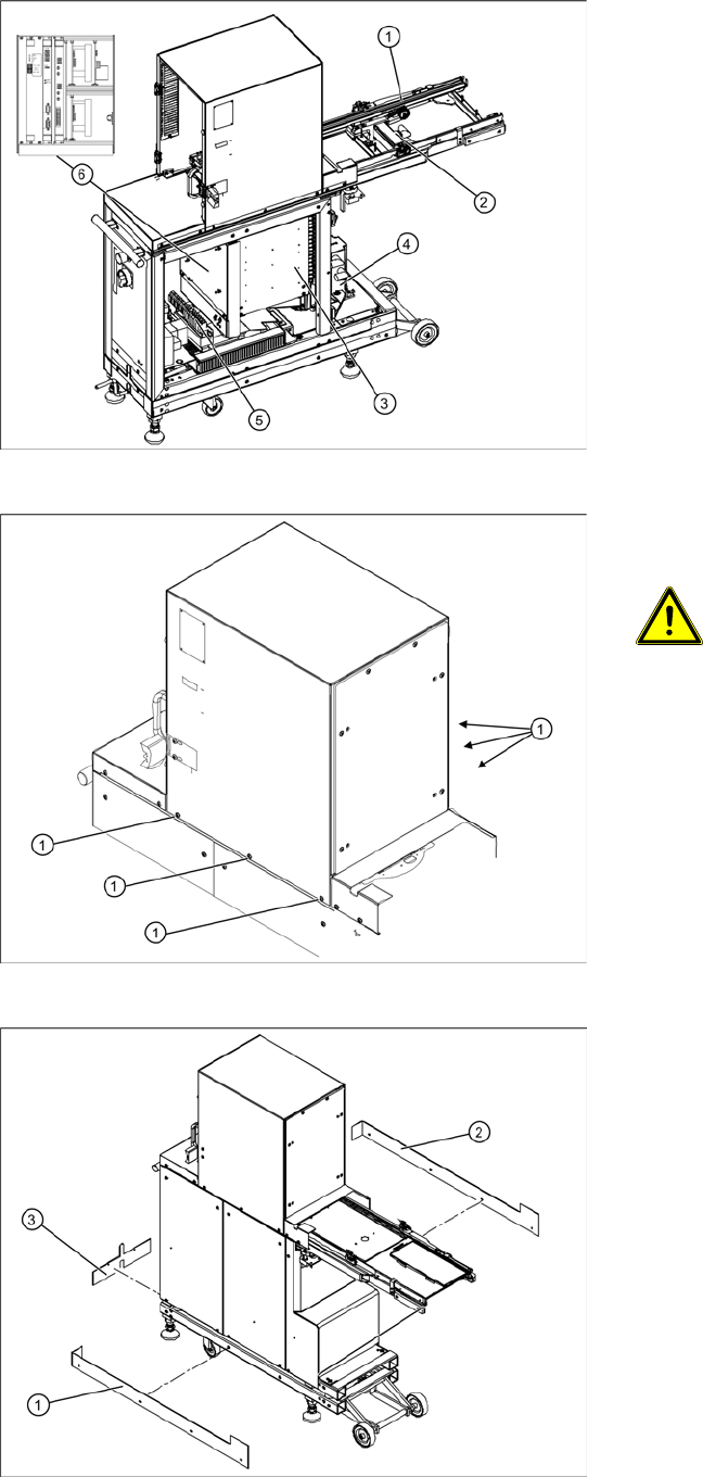
3.2 Overview of Main Assemblies
Overview
1. Feed axis
2. Drive unit – feed axis
3. Lifting axis with tower
4. Drive unit – lifting axis
5. Power supply
6. Control unit (position when fitted)
Screws sealed with locking varnish on
tower
ATTENTION: Do not open screws on
the tower which have been sealed
with locking varnish
The tower is set with these 6 screws (1)
at the factory.
X If you open these screws, the WPC4
must be taken to Siemens AG for
readjustment.
Bottom cover plates
If the WPC4 is configured for high machine
heights, additional cover plates will be attached to
the base.
1. Right-hand cover
2. Left-hand cover
3. Front cover
You may need to remove these covers before
performing service work.