WPC4 services manual - 第27页
Replacing Spare Parts Setting the Feed Axis Belt Tension Drive Unit – Feed Axis Service Manual SIPLACE WPC4 27 3.4.5 Setting the Feed Axis Belt T ension Tools/equipment Setting gauge, small [03052363- 02] (1) Setting…
Replacing Spare Parts
Drive Unit – Feed Axis Replacing the Feed Axis Toothed Belt [03047690-xx]
26 Service Manual SIPLACE WPC4
See also:
J 4.2.1 Procedure - Calibrating the Feed Axis [J64]
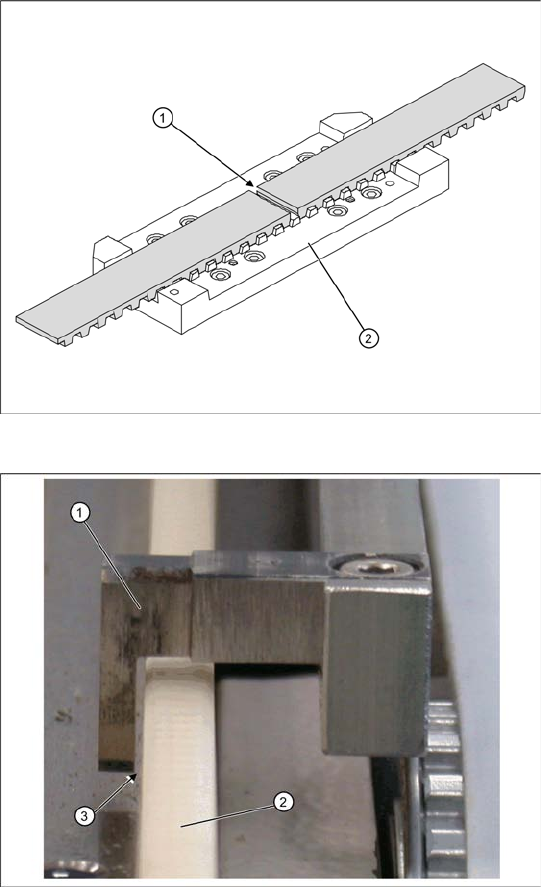
X The two ends of the toothed belt must be
inserted into the clamping unit (2) so that the
clamping unit teeth engage with the belt teeth.
The two ends must meet (1).
X Note the length of the new toothed belt. The
toothed belt is 2120 mm long/ number of teeth:
424.
X If the belt is too long, shorten it to the correct
length.
X Fit the catch unit onto the clamping unit (2).
Tighten the 4 fastening screws crosswise.
Final work
The catch unit must be adjusted so that it is
straight (adjust at fastening screws). Make sure
that it does not rub against any parts or jam at any
point of the travel range.
X Set the catch (1) to a distance of approx. 0.5
mm (3) to the white plastic guidance (2).
X Push the catch back and forth along the travel
range, to check that it does not rub against any
parts or jam at any point.
X Set the correct belt tension. See also Section
3.4.5 Setting the Feed Axis Belt Tension
[J27].
X Calibrate the feed axis.
Replacing Spare Parts
Setting the Feed Axis Belt Tension Drive Unit – Feed Axis
Service Manual SIPLACE WPC4
27
3.4.5 Setting the Feed Axis Belt Tension
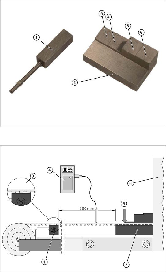
Tools/equipment
Setting gauge, small [03052363-02] (1)
Setting gauge, large, collision light barriers
[03051814-01] (2)
Belt tension measuring device [00326015-01]
with instruction guide
Measurement setup - measuring the feed
axis belt tension
Note: the bridge cover has been removed in this
diagram.
X Push the two setting gauges (1) + (2) under
the toothed belt, at a distance of 360 mm.
The large setting gauge (2) is against the
tower cover (6).
The teeth of the toothed belt (3) must lie on the
setting gauge.
X Press the large setting scale downwards with
a suitable object or with your finger, so that the
toothed belt lies on the gauge (5).
X Set the belt tension. To do this, gently pull the
toothed belt or tap it with an Allen wrench, so
that it starts swinging and then measure the
value with the belt tension measuring device.
The belt tension must be 105 Hz. +/-5 Hz..
Replacing Spare Parts
Control Unit and Power Supply Unit Setting the Feed Axis Belt Tension
28 Service Manual SIPLACE WPC4
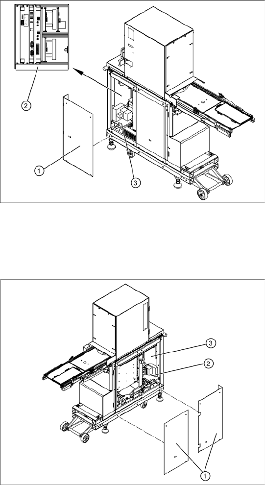
3.5 Control Unit and Power Supply Unit
Front side
X Remove the 4 screws (1) fastening the side
covers. Underneath, you will see the front end
of the control unit (2) and the front end of the
power supply unit (3).
The front end of the control unit contains the
Servo and axis controller boards
Ballast circuit
Power supply board
Controller board
The front end or installation plate of the power
supply unit contains the
Protective contactor combination SSK – K1
Contactors K2/K3
Primary and secondary transformer fuses
Back
X Remove the 8 screws (1) fastening the two
side covers. Underneath, you will see the back
of the control unit (3) and the back of the power
supply unit (2).
The back of the control unit contains the terminal
strips and the plug-and-socket connections,
the limit switches, sensors and light barriers
The drive motors (lifting and feed axis)
The fan connection etc.
The back part or installation plate of the power
supply contains the
Inrush current limitation board A1 with K4
Line filter for 3-phase system
Rectifier bridge
Transformer