WPC4 services manual - 第34页
Replacing Spare Parts Control Unit and Power Supply Unit Control Unit 34 Service Manual SIPLACE WPC4 Installation X During installation, make sure you fit the pa rts in the co rrect position (front/back). X Carefully lif…
Replacing Spare Parts
Control Unit Control Unit and Power Supply Unit
Service Manual SIPLACE WPC4
33
3.5.1.7 Replacing the Complete Control Unit [03047226-xx]
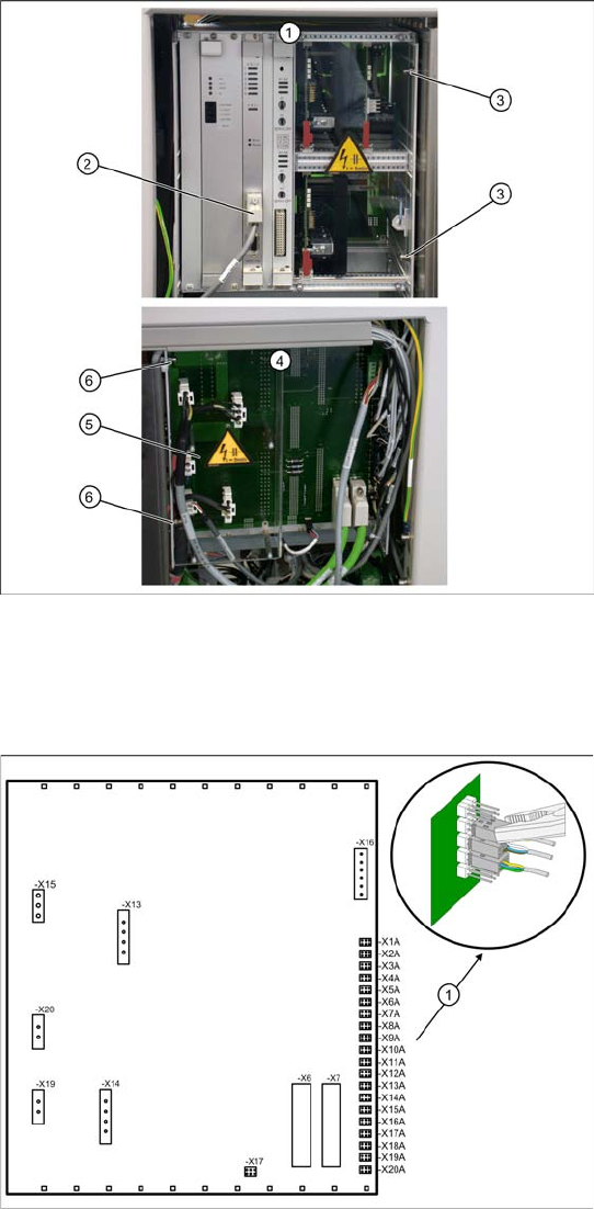
Overview
1. Control unit – front
2. CAN bus connection on controller board
3. 2 x cap nuts on the front
4. Control unit – back plane
5. Plexiglass cover
6. 2 x cap nuts on the back
Spare part
WPC control unit, compl. [03047226-01]
Removal
X Wear the ESD wristband.
X Loosen the 4 screws fastening the plexiglass
cover (5) to the back plane and remove this.
X Check whether all cables are labeled.
X Make sure that you are able to correctly assign
all cables and plugs. Where necessary, label
cables, plugs and connections for easier
reconnection later.
X Unplug the CAN bus cable from the front of the
controller board.
Control unit back plane – details
1. Connections for limit switches, sensors and
light barriers
X For connection details and complete circuit
diagrams, please refer to the following
documentation:
SIPLACE D1 detailed circuit diagrams
[00194841-xx] German
SIPLACE D1 detailed circuit diagrams
[00194841-xx] English
X Carefully unplug connections X1A to X20A on
the terminal strip (proximity switch, sensors
etc.) with a suitable pair of pliers (e.g.
combination pliers) (1). Make sure that you do
not bend the contact pins.
X Unplug the remaining cables, plugs and
connections.
Replacing Spare Parts
Control Unit and Power Supply Unit Control Unit
34 Service Manual SIPLACE WPC4
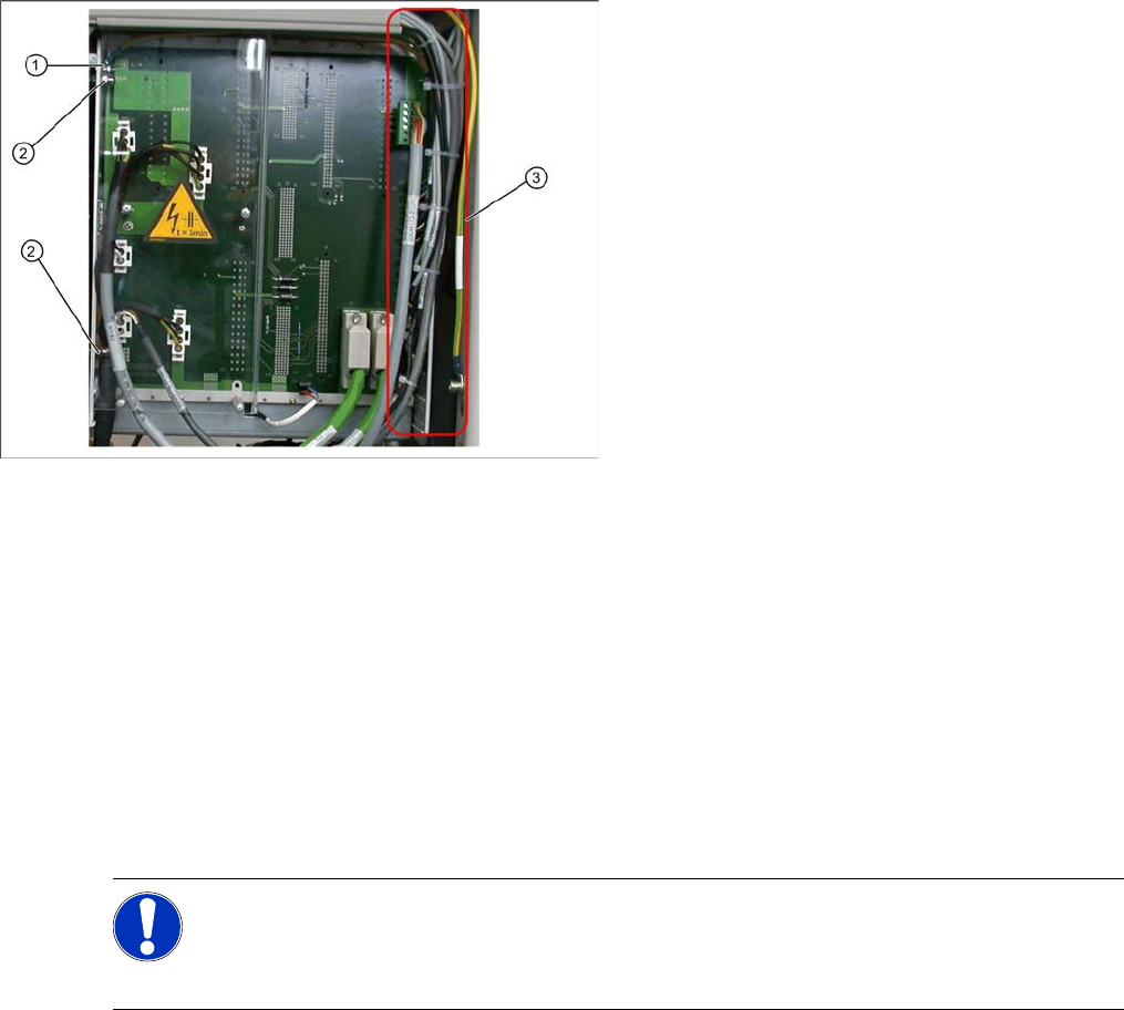
Installation
X During installation, make sure you fit the parts in the correct position (front/back).
X Carefully lift the new control unit onto the threaded pins and fix in place with the 4 cap nuts.
X Restore all electrical connections and plug in the ground cable (1) again.
X Run the cables neatly inside the control unit (3) so that they do not interfere with any other parts.
X Fix the cables with cable ties.
X Fit the plexiglass cover.
Settings
X Use SITEST to check that the sensors have a correct cable assignment. To do this, open the SITEST
main view and select the function=>
SITEST inputs/outputs 1
. Trigger the individual limit switches
and sensors manually, to check whether the correct input is activated.
X Disconnect the control unit ground cable (1)
from the WPC4 frame.
X Loosen the 2 cap nuts (2) from the threaded
pins on the back plane side of the control unit.
X Loosen the 2 cap nuts from the threaded pins
on the front side of the control unit.
X Carefully pull the control unit out towards the
front.
NOTE: Machine data and calibration
If you have also replaced the controller board or axis controller board, together with the control
unit, you will need to perform a firmware download (BIOS and application).
If there is no current MA file available, you will need to completely recalibrate the WPC4.
Replacing Spare Parts
Control Unit Control Unit and Power Supply Unit
Service Manual SIPLACE WPC4
35
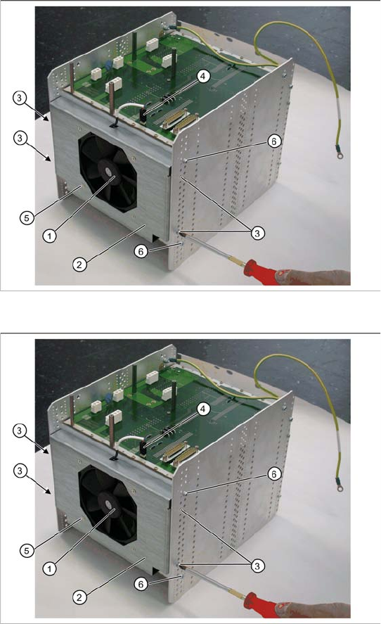
3.5.1.8 Replacing the Fan [03051368-xx]
X Lever the mounting frame (2) out of the control unit holes with a suitable tool (e.g. screwdriver).
X Remove the mounting frame with fan.
X Mark the installation position of the fan (1) in the mounting frame. Make a note of the direction in
which air is blown out! The fan takes air from below and blows it into the inside of the control unit.
X Loosen the 4 screws (5) fastening the fan (1) to the mounting frame.
X Remove the fan.
Installation
X Fit the fan in the mounting frame. Note the position of the connection cable.
X Carefully lever the mounting frame with its openings into the holes.
X Fit the mounting frame with the fan in the control unit.
X Tighten the two screws (6) on the control unit and reconnect to the power supply.
X Fit the complete control unit (see Section 3.5.1.7 Replacing the Complete Control Unit [03047226-
xx] [J33]).
Spare part
Control unit fan [03051368-01]
Overview
The fan (1) is located on the underside of the
control unit and is fitted with the help of a mounting
frame (2).
1. Fan
2. Mounting frame
3. 4 x mounting frame fastening screws
4. Electrical connection for fan
5. 4 x fastening screws for fan on mounting frame
Removal
X Dismantle the complete control unit (see
Section 3.5.1.7 Replacing the Complete Con-
trol Unit [03047226-xx] [J33]).
X Unplug the connection cable (4) and the back
plane X17.
X Mark the installation position of the mounting
frame (2) on the relevant control unit holes.
X Loosen the 4 fastening screws (3) on the
mounting frame (2).
X The mounting frame (2) can be levered more
easily out of the holes, if you also loosen the 2
screws (6) on the control unit.