WPC4 services manual - 第43页
Replacing Spare Parts Introduction Limit Switches, Sensors and Light Barriers Service Manual SIPLACE WPC4 43 Lifting axis – order of settings If the limit switches or sensors are replaced, you will need to recalibrate or…
Replacing Spare Parts
Limit Switches, Sensors and Light Barriers Introduction
42 Service Manual SIPLACE WPC4
3.6.1.3 Requirements for Settings
NOTE: The collision light barriers for height checks must not trigger during calibration
During calibration of the reference sensors and the limits switches, make sure that the collision
light barriers do not trigger without good reason. If this does happen, the calibration process will
stop and no values or invalid values will be calculated.
X During calibration, make sure that the light beam of the collision light barriers is not
interrupted by objects etc..
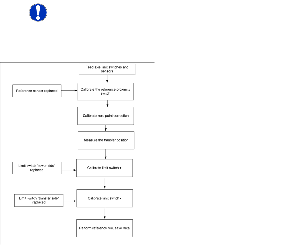
Feed axis – order of settings
If the limit switches or sensors are replaced, you
will need to recalibrate or reset these. Make sure
that you adhere to the correct order. For example,
if the reference sensor is replaced, the subsequent
calibrations, such as "transfer position“ limit switch
+“ etc., must be performed.
Replacing Spare Parts
Introduction Limit Switches, Sensors and Light Barriers
Service Manual SIPLACE WPC4
43
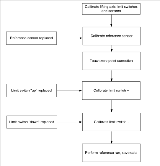
Lifting axis – order of settings
If the limit switches or sensors are replaced, you
will need to recalibrate or reset these. Make sure
that you adhere to the correct order. For example,
if the reference sensor is replaced, the subsequent
calibrations, such as "transfer position“ limit switch
+“ etc., must be performed.
Replacing Spare Parts
Limit Switches, Sensors and Light Barriers Replacing the WPTC Available Sensor [03047283-xx]
44 Service Manual SIPLACE WPC4
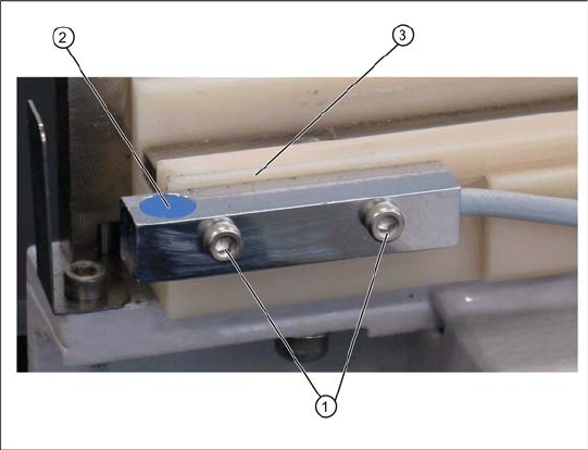
3.6.2 Replacing the WPTC Available Sensor [03047283-xx]
Removal/installation
X Loosen the two fastening screws (1) on the sensor.
X Loosen the cable clamps and remove the cable ties.
X Unthread the connection cable as far as the control unit back plane and unplug it from the terminal
strip.
X Fit the sensor so that the sensor surface (2) points upwards.
X Align the sensor parallel to the white guidance rail (3).
X Restore the electrical connection and fix the connection cable into place.
Settings
X Check the sensor function.
X To do this, push a waffle pack tray carrier (WPTC) by hand over the sensor. The LED on the sensor
will show the status:
LED shines = switched
LED does not shine = not switched.
X Use SITEST to check whether the correct output was switched.
X To do this, open the SITEST main view and select the function=>
SITEST inputs/outputs 1
.
The display
WPTC available sensor
must be active for this sensor.
X Remove the waffle pack tray carrier.
The relevant display must be off.
1. Fastening screws
2. WPTC available sensor
3. Guidance rail
Spare part
Proximity switch for WPC available sensor
[03047283-01]