00190913-02.pdf - 第23页
Retrofit ting Ins tructi ons Flux Dis penser (Optional) on S IPLACE 80F 4 Edition 08/ 98 Page 7 from 14 3.3 Installing the Flux Dispenser Head 3.3.1 Installing the Flux Dispenser Head • Fasten the dispenser head to the c…
Flux Dispenser (Optional) on SIPLACE 80F
4
Retrofitting Instructions
Edition 08/98
Page
6
from 14
3 Installing the Optional Flux Dispenser
3.1 Preparations
• Turn the machine off at the main switch and pull out the power supply plug.
• Remove set-up from the right-hand component table
• If installed, remove the(optional) wafflepack changer from the machine.
3.2 Exchanging the Camera Holder
• Dismantle the IC placement head from the machine. To do so, disconnect the electrical and pneumatic
connections and unscrew the fastening screws.
• Dismantle the scanning head for the X-axis.
• Loosen the clamping screw for the X-axis end-position proximity switch and remove the proximity switch.
• Loosen the adjusting screw for the friction block.
• Remove the camera for the bottom portal.
• Remove the camera holder.
• Remove the friction block holder from the camera holder you just removed and mount it on the new
camera holder
• Install the new camera holder.
• Re-install the camera for the bottom portal.
• Carefully screw in the adjusting screw with two fingers until the friction block has been moved gently
against the X-axis linear guide (locate spring pressure point).
• Turn the adjusting screw clockwise 4 revolutions. The friction block will then be pressed against the X-
axis linear guide with a defined pressure.
• Re-install the end-position proximity switch. Check the distance (0.5 mm) from the proximity switch to the
switching plate.
• Re-install the scanning head for the X-axis. Check the distance (0.4 mm) from the scanning head to the
X-axis scale.
• Shorten the plastic hose for the compressed air supply for the Z-axis clamp 100 mm.
• Slip the “Y” tube coupler onto the shortened end of the supply hose. Pay attention to the direction of flow.
• Connect the 100 mm section to one branch of the “Y” tube connector and the 0.5 m plastic hose to the
other tube connector.
• Re-install the IC head and restore the electrical connections.
• Connect the short branch of the plastic hose to the solenoid valve of the Z-axis clamp.
• Restore the compressed air connection to the vacuum generator.
Retrofitting Instructions Flux Dispenser (Optional) on SIPLACE 80F
4
Edition 08/98
Page
7
from
14
3.3 Installing the Flux Dispenser Head
3.3.1 Installing the Flux Dispenser Head
• Fasten the dispenser head to the camera holder with 4 M5 x 12 socket head cap screws.
• Exchange component illumination board Y0021 for component illumination board, flux, Y1033.
• Remove the cover plate under the pump housing.
• Connect X1 of the conversion board, flux, to X8 of the component illumination board, flux. Use the cable
“Flux monitoring, 00323903-01.
• Connect X95 of the flux pump to X7 of component illumination board, flux. Use the cable “Control, flux
pump”, 00323902-01.
• Re-install the cover plate.
• Remove the U-shaped machine casing for conversion PC board C0003.
• Plug the cable “V24 Flux” onto unused board slot X26, and run the other end through the machine base
to the control unit.
• Slip the cable onto connector X4 of the communication module.
• Re-install the U-shaped casing for the conversion PC board.
Flux Dispenser (Optional) on SIPLACE 80F
4
Retrofitting Instructions
Edition 08/98
Page
8
from 14
3.3.2 Tubing for Flux Dispenser Head
• Run the long branch of the compressed air hose through the 2 holes in flux dispenser head
• Loosen the clamping force on the pipette tube by backing the centering pipette out about 3 to 4
revolutions.
• Insert the pipette tube into the dosing cylinder from the top.
• Fasten the pipette tube in place by retightening the centering pipette. The pipette tube should project
about 3 mm.
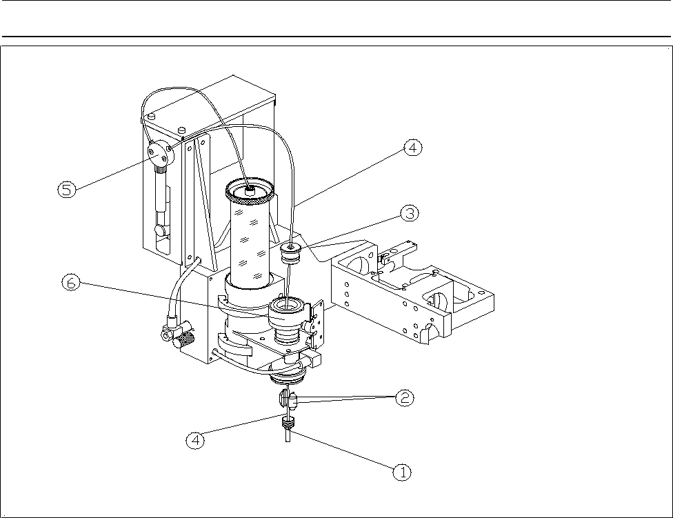
• Run the tubing for flux dispenser head as shown in Fig. 1.
Note
Run the tubes in such a manner that they cannot drag on the hood of the machine.
Figure 1 Flux Dispenser Head
− Key to Fig. 1
Centering pipette ô Clamping piece
í Cylinder cover ÷ Dosing hose with pipette tube
û Valve and syringe ø Cylinder