00190913-02.pdf - 第26页
Flux Dis penser (Optional) on S IPLACE 80F 4 Retrofit ting Ins tructi ons Edition 08/ 98 Page 10 from 14 • Re-install the reject box. 3.5 Converting the Conveyor Control 3.5.1 For Single Conveyor (Stationary Side on Righ…
Retrofitting Instructions Flux Dispenser (Optional) on SIPLACE 80F
4
Edition 08/98
Page
9
from
14
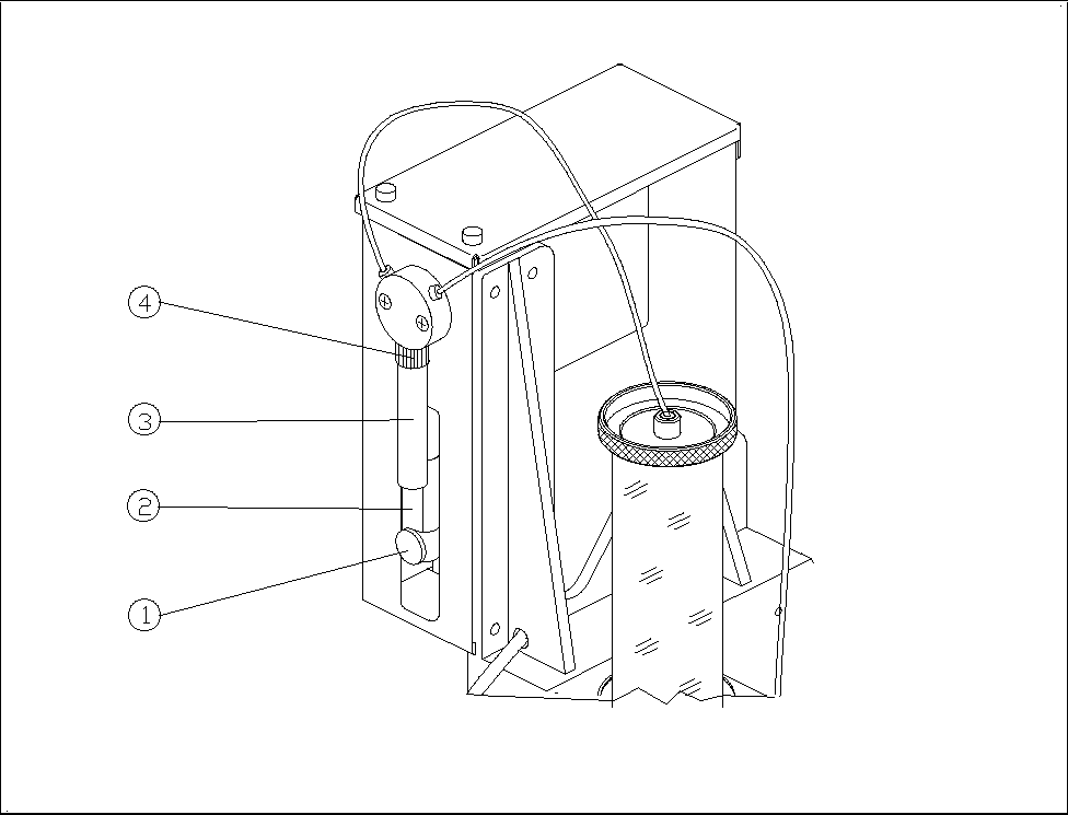
3.3.3 Installing the Syringe on the Flux Dispenser Head
• Insert the dosing piston into the syringe.
• Screw the syringe into the valve with the retaining nut.
• Pull the dosing piston down and fasten it in place with the knurled thumb screw.
Figure 2 Syringe
− Key to Fig. 2
Knurled thumb screw ô Dosing piston
í Syringe ÷ Retaining nut
3.4 Installing the Rinsing Tank
• Remove the IC head reject box.
• Remove the reject box holder.
• Install the new reject box holder with rinsing tank holder.
• Insert a centrifugal tube into the rinsing tank holder.
• Slip the brush onto the centrifugal tube.
Flux Dispenser (Optional) on SIPLACE 80F
4
Retrofitting Instructions
Edition 08/98
Page
10
from 14
• Re-install the reject box.
3.5 Converting the Conveyor Control
3.5.1 For Single Conveyor (Stationary Side on Right or Left)
Control unit for PC board handling
• The 4-channel half bridge rectifier PC board in the control unit must be exchanged for the digital 6-
channel half bridge rectifier PC board (00326606-01).
• The 64-terminal base connector is exchanged for the newly coded base connector (00332396-01).
• The 14-terminal connection cable Y0651 is exchanged for the 30-terminal connection cable
(00332439-01). This cable divides into 2 branches at one end. The one with the 14-terminal
connector is run to the machine base via the base plate of PC board handling. The other one runs
on the base plate to terminal point A4/pin 13.
Stationary side cheek of output belt:
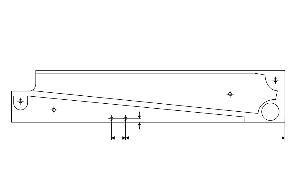
• Two threaded holes must be cut in the cheek to attach the light barrier (see Fig. 3).
• The light barrier and the distance plate are both fastened in these threaded holes.
• The light barrier is connected as follows on the base plate:
black core (signal) to terminal distributor A4/pin 13
blue core (ground) to terminal distributor A4/pin 20
brown/pink (br: 24 V= / pink: function high-active) together to terminal distributor A3/pin 10
Figure 3 Holes for Light Barrier
35 mm 300 mm
5 mm
2x M
3

Retrofitting Instructions Flux Dispenser (Optional) on SIPLACE 80F
4
Edition 08/98
Page
11
from
14
3.5.2 For Dual Conveyor (Stationary Side Right or Left)
Control unit for PC board handling:
• The 4-channel half bridge rectifier PC board in the control unit must be exchanged for the digital 6-
channel half-bridge rectifier PC board (00326606-01).
Following switch positions must be set: Switch 1
Ø
OFF
Switch 2
Ø
OFF
• The 64-terminal basic connector is exchanged for the newly coded basic connector (00332396-01).
• The 26-terminal connection cable of the conveyor belts is exchange for the 30-terminal connection
cable (00331297-01). This cable runs from the basic connector of the half bridge rectifier PC board
to the conversion PC board, connector X6.
• The conversion PC board must correspond to production status 03 at least. If necessary, the
conversion PC board must be exchanged.
Stationary cheeks of the output belts:
• Two threaded holes must be made in the cheeks for each light barrier (see Fig. 3).
• The light barriers for output belt 1 (00330946-01) and/or output belt 2 (00330949-01) must be
attached at these threaded holes together with the distance plates.
• The light barrier for output belt 1 is connected to connector X54 on the conversion PC board. The
light barrier for output belt 2 is connected to connector X55.
3.6 Adjustments
2.6.1 Height of the Pipette Tube
Adjust the height of the flux dispenser head such that the distance between PC board and pipette tube is 1 to
2 mm when the Z-axis is in the bottom position.
• To adjust the height of the head, remove the cover under the pump housing and back out the 2 socket
head cap screws.
• After you have adjusted the height of the head, retighten the 2 socket head cap screws and fasten the
cover.
3.6.2 Operating Points of Light Barrier for Fill Level
Set the operating points such that both LEDs on the “Component illumination board, flux” light up when the
centrifugal tube is full or do not light up when the centrifugal tube is empty.
• Insert an empty storage bin in the holder on the flux dispenser head.
• Turn R26 and mark the position at which LED V21 turns on or off.
• Turn R27 and mark the position at which the LED turns on or off.
NOTE
If you cannot turn a diode on, mark the right-handf stop on the potentiometer. However, if a light barrier
cannot be turned off, a fault exists.