00190913-02.pdf - 第28页
Flux Dis penser (Optional) on S IPLACE 80F 4 Retrofit ting Ins tructi ons Edition 08/ 98 Page 12 from 14 • Insert a full storage bin in the holder on the flux dispenser head. • Turn R26 and mark the position at which LED…

Retrofitting Instructions Flux Dispenser (Optional) on SIPLACE 80F
4
Edition 08/98
Page
11
from
14
3.5.2 For Dual Conveyor (Stationary Side Right or Left)
Control unit for PC board handling:
• The 4-channel half bridge rectifier PC board in the control unit must be exchanged for the digital 6-
channel half-bridge rectifier PC board (00326606-01).
Following switch positions must be set: Switch 1
Ø
OFF
Switch 2
Ø
OFF
• The 64-terminal basic connector is exchanged for the newly coded basic connector (00332396-01).
• The 26-terminal connection cable of the conveyor belts is exchange for the 30-terminal connection
cable (00331297-01). This cable runs from the basic connector of the half bridge rectifier PC board
to the conversion PC board, connector X6.
• The conversion PC board must correspond to production status 03 at least. If necessary, the
conversion PC board must be exchanged.
Stationary cheeks of the output belts:
• Two threaded holes must be made in the cheeks for each light barrier (see Fig. 3).
• The light barriers for output belt 1 (00330946-01) and/or output belt 2 (00330949-01) must be
attached at these threaded holes together with the distance plates.
• The light barrier for output belt 1 is connected to connector X54 on the conversion PC board. The
light barrier for output belt 2 is connected to connector X55.
3.6 Adjustments
2.6.1 Height of the Pipette Tube
Adjust the height of the flux dispenser head such that the distance between PC board and pipette tube is 1 to
2 mm when the Z-axis is in the bottom position.
• To adjust the height of the head, remove the cover under the pump housing and back out the 2 socket
head cap screws.
• After you have adjusted the height of the head, retighten the 2 socket head cap screws and fasten the
cover.
3.6.2 Operating Points of Light Barrier for Fill Level
Set the operating points such that both LEDs on the “Component illumination board, flux” light up when the
centrifugal tube is full or do not light up when the centrifugal tube is empty.
• Insert an empty storage bin in the holder on the flux dispenser head.
• Turn R26 and mark the position at which LED V21 turns on or off.
• Turn R27 and mark the position at which the LED turns on or off.
NOTE
If you cannot turn a diode on, mark the right-handf stop on the potentiometer. However, if a light barrier
cannot be turned off, a fault exists.
Flux Dispenser (Optional) on SIPLACE 80F
4
Retrofitting Instructions
Edition 08/98
Page
12
from 14
• Insert a full storage bin in the holder on the flux dispenser head.
• Turn R26 and mark the position at which LED V21 turns on or off.
• Turn R27 and mark the position at which LED V22 turns on or off.
NOTE
If you cannot turn a diode on, mark the right-hand stop on the potentiometer. However, if a light barrier cannot
be turned off, a fault exists.
• As the final step, each of the 2 potentiometers, R26 and R27, is set in the middle between the 2 marks.
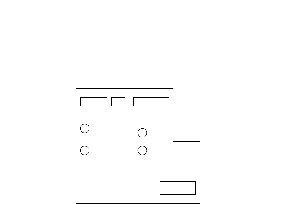
X4 X5 X3
X8
X7
Figure 4 “Component Illumination Board, Flux”
V21
V22
R27
R26

Retrofitting Instructions Flux Dispenser (Optional) on SIPLACE 80F
4
Edition 08/98
Page
13
from
14
3.7 Calibration
Activate the option flux applicator in the menu Miscellaneous/Machine Config. in SITEST
3.7.1 Distance of Pipette Tube <-> Component Camera Revolver Head
• Slip the centering pin onto the pipette tube.
• Press the sealing compound onto a PC board and move the board into the center conveyor.
• Teach the flux dispenser head to a position over the sealing compound and press the centering pin down
into the sealing compound.
• Record the this X- and Y-position.
• Teach the PCB camera to the centered position over the impression in the sealing compound.
• Ascertain the difference between the current X- or Y-position versus the recorded X- or Y-position.
• Add the camera offset, factoring in the prefix of the result, and enter the value in the appropriate field in
SITEST.
3.7.2 Determining the Rinsing Position
• By manually moving the portal by hand, move the pipette tube to the rinsing position.
• Plug the axis test box onto the X/Y-star axis PC board.
• Read the X- and Y-positions from the axis test box and record their readings.
• Calculate the X- and Y-values of the rinsing position on the basis of the following example:
X- value = (Value of axis test box + Distance between pipette tube and compon. camera offset) x 2.5
= e.g., (214251 digit + 276 digit ) x 2.5
= 536318 µm
Y-value = (Value of axis test box - Distance between pipette tube to component camera offset) x 2.5
= (340255 digit - 103607 digit ) x 2.5
= 534938 µm
• Enter the calculated values in Flux.ma.
DANGER O O O
Perform the following test of the rinsing position with just the “Key-operated switch ON” function, since there is
danger of a crash with the flux dispenser head if the rinsing position is entered incorrectly.