00193893-04.pdf - 第98页
2 Retrofit instructions - SIPLACE HF series head re confi guration kits SIPLACE HF Series Head Reconfiguration Kits 05/2006 Edition 98 : Set the DIP switch on the processor board according to the information be low . 2 A…
SIPLACE HF Series Head Reconfiguration Kits 2 Retrofit instructions - SIPLACE HF series head reconfiguration kits
05/2006 Edition
97
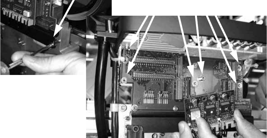
: Plug the 03019066-xx DLM2 head adapter from below into the head interface board, and
screw in place.
: Plug the 00344488-xx modular SM board onto the DLM2 head adapter and fix in place with the
appropriate screws.
2
8 bit variant 2
: Then plug in the 80C515 HF processor board (03013014-xx) and screw in place.
2
2
2
2
2
2
2
2
2
2
2
2
2
2
2 Retrofit instructions - SIPLACE HF series head reconfiguration kits SIPLACE HF Series Head Reconfiguration Kits
05/2006 Edition
98
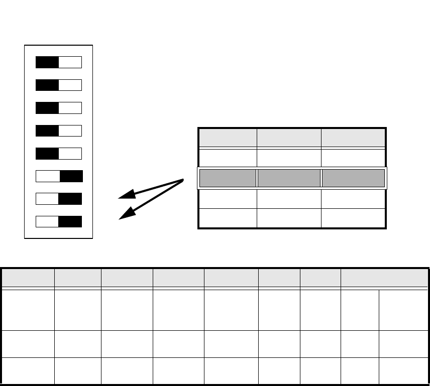
: Set the DIP switch on the processor board according to the information below.
2
Abb. 2.5.1 Table: DIP switch
2
2
2
2
2
2
2
Standard OFF OFF OFF OFF ON ON CAN_address
Switch-
setting
1
CAN_R120
2
EPROM_WE
3
Test_Mode
4
CAN_ERR_
SWITCH
5
Jumper 5
6
Jumper 6
7
CAN_ID1
8
CAN_ID0
ON X
See
above
See above
OFF X X X X X
See
above
See above
DIP Schalter
ON
78123456
Gantries Switch 7 Switch 8
Gantry 1 ON ON
Gantry 2 ON OFF
Gantry 3 OFF ON
Gantry 4 OFF OFF
SIPLACE HF Series Head Reconfiguration Kits 2 Retrofit instructions - SIPLACE HF series head reconfiguration kits
05/2006 Edition
99
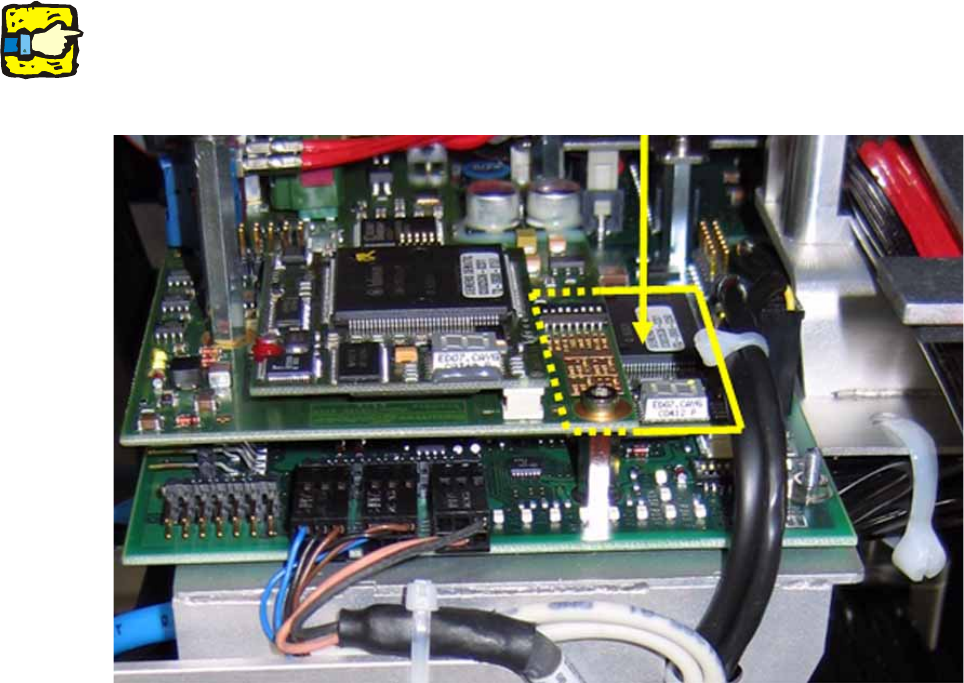
16 bit variant 2
DO NOT insert the 8 bit processor on the head adapter (see previous item) if the head interface
board is equipped with a piggyback processor TQM 167 (see photograph below). 2
The processor on the head interface then controls the placement head. 2
2
2
2
Do not confuse the vision interface with the head interface. 2
The vision interface is seated above the head interface and always has a piggyback processor
TQM 167. 2
2
2
2
2
2
2
2
2
2
2
2