0771445_7708_Mar2018_077144500.pdf - 第13页
Model 7708 M ultiplexer M odule Instructions for use w ith DAQ6510 077144500 / April 2018 13 This verification pr ocedure requires t hat the DAQ6510 be within its calibration inte rval. Module verification test procedure…
Model 7708 Multiplexer Module Instructions for use with DAQ6510
12 077144500 / April 2018
Before installing or removing a switching module, make sure the DAQ6510 power is turned
off and disconnected from line power. Failure to comply may result in incorrect operation and
loss of data in the memory.
Required equipment:
▪ Medium flat-blade screwdriver
▪ Medium Phillips screwdriver
To remove switching module from the DAQ6510:
1. Turn off the DAQ6510.
2. Disconnect the power cord from the power source.
3. Disconnect the power cord and any other cables that are connected to the rear panel.
4. Position the DAQ6510 so you are facing the rear panel.
5. Use the screwdriver to loosen the mounting screws that secure the switching module to the mainframe.
6. Carefully remove the switching module.
7. Install a slot plate or switching module in the empty slot.
8. Reconnect the power cord and any other cables.
Operation
This switching module does not support current measurements. If the instrument has the TERMINALS switch
set to REAR and you are working with the slot that contains this switching module, the AC , DC , and digitize
current functions are not available. You can measure current using the front panel or using another slot that
contains a switching module that supports the AC , DC , and digitize current measurements.
If you use remote commands to attempt to measure current when configuring a channel, an error is returned.
Performance verification
The performance of the module is tested by verifying the accuracy of measurements made through the module.
If verification limits are met through the front-panel terminals of the DAQ6510, they should also be met through
the module.
Do not attempt to perform this procedure unless qualified to do so. Failure to recognize and
observe normal safety precautions could result in personal injury or death.
Measurement accuracy through the module should only be verified after instrument accuracy has
been verified through the front-panel terminals of the DAQ6510. Refer to the DAQ6510 Calibration
and Adjustment manual (documentation number DAQ6510-905-01) for verification information.

Model 7708 Multiplexer Module Instructions for use with DAQ6510
077144500 / April 2018 13
This verification procedure requires that the DAQ6510 be within its calibration interval.
Module verification test procedures include:
▪ DC volts
▪ AC volts
▪ Resistance
▪ Temperature
▪ Frequency
▪ Ratio and average
Make sure that you perform the verification tests using the following conditions:
▪ Under the proper environmental conditions
▪ After the specified warm-up period
▪ With connections made to the correct input terminals
▪ Using the correct line voltage
▪ With the TERMINALS switch in the REAR position
▪ With the proper calibration equipment and the reading limits provided with the verification procedures. See
Calculating resistance reading limits (on page 14) for more information.
Environmental conditions
Conduct your performance verification procedures in a test environment that has:
▪ An ambient temperature of 18 °C to 28 °C.
▪ A relative humidity of less than 80% unless otherwise noted.
Warm-up period
Allow the DAQ6510 to warm up for at least one hour before verifying the module.
If the instrument has been subjected to temperature extremes (those outside the ranges stated above), allow
additional time for the internal temperature of the instrument to stabilize. Typically, allow one extra hour to
stabilize an instrument that is 10 °C outside the specified temperature range.
Allow the test equipment to warm up for the minimum time specified by the manufacturer.
Example reading limit calculation
The following is an example of how reading limits have been calculated. Assume you are testing the 10 VDC
range using a 10 V input value. Using the DAQ6510 one-year accuracy specification for 10 VDC of ± (25 ppm
of reading + 5 ppm of range), the calculated limits are:
Reading limits = 10 V ± [(10 V 25 ppm) + (10 V 5 ppm)]
Reading limits = 10 V ± (0.00025 + 0.00005)
Reading limits = 10 V ± 0.00030 V
Reading limits = 9.99970 V to 10.00030 V
Model 7708 Multiplexer Module Instructions for use with DAQ6510
14 077144500 / April 2018
Calculating resistance reading limits
Resistance reading limits must be recalculated based on the actual calibration resistance values supplied by
the equipment manufacturer. Calculations are performed in the same manner as shown in the previous
example, except that you should use the actual calibration resistance values instead of the nominal values
when performing your calculations.
For example, assume that you are testing the 10 kΩ range using an actual 10.03 kΩ calibration resistance
value. Using DAQ6510 one-year 10 kΩ range accuracy of ± (75 ppm of reading + 6 ppm of range), the
calculated reading limits are:
Reading limits = 10.03 kΩ ± [(10.03 kΩ 75 ppm) + (10 kΩ 6 ppm)]
Reading limits = 10.02929 kΩ to 10.03081 kΩ
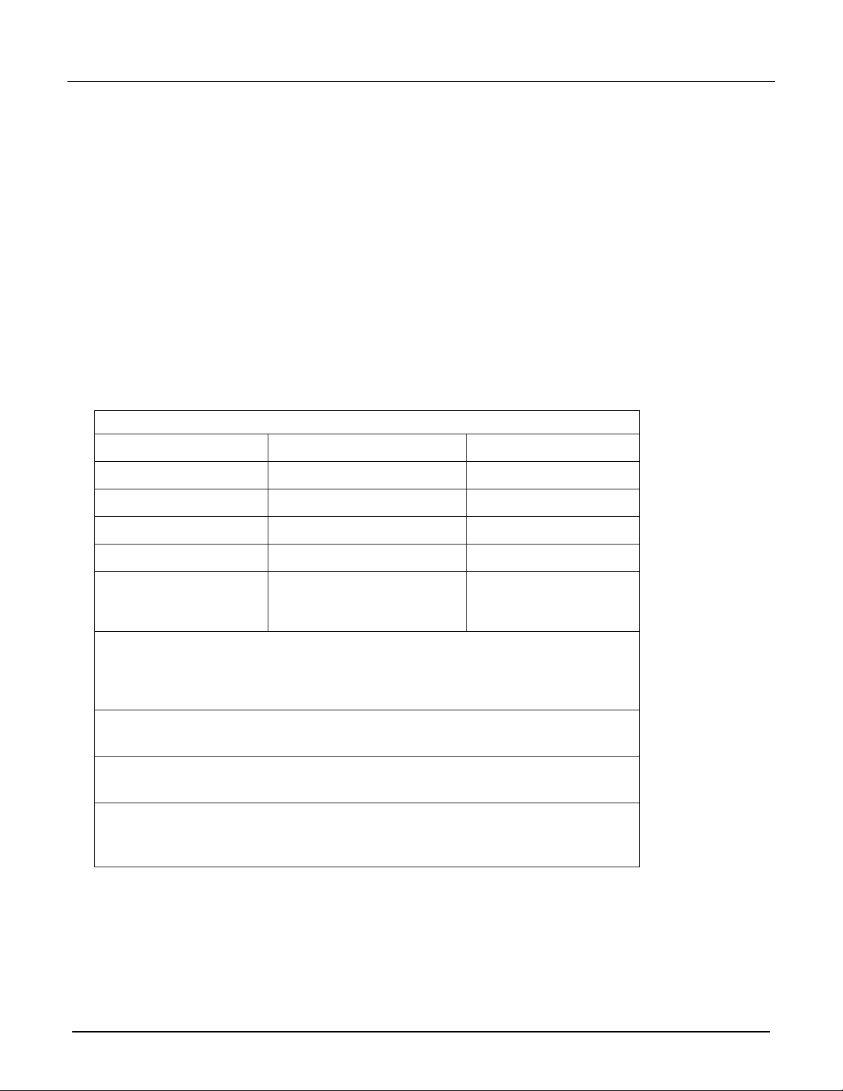
Recommended test equipment
The table below summarizes recommended verification equipment. You can use alternate equipment if that
equipment has specifications that meet or exceed those listed below. Be aware that calibrator uncertainty adds
to the uncertainty of each measurement.
Fluke 5700A Calibrator:
DC voltage
AC voltage (1 kHz, 50 kHz)
Resistance
100 mV: ±14 ppm
100 mV: ±200 ppm
100 Ω: ±17 ppm
1.0 V: ±7 ppm
1.0 V: ±82 ppm
1 kΩ: ±12 ppm
10 V: ±5 ppm
10 V: ±82 ppm
10 kΩ: ±11 ppm
100 V: ±7 ppm
100 V: ±90 ppm
100 kΩ: ±13 ppm
1000 V: ±9 ppm
700 V: ±85 ppm
1 MΩ: ±18 ppm
10 MΩ: ±37 ppm
100 MΩ: ±120 ppm
Fluke 5725A Amplifier
AC Voltage, 50 kHz: 700 V, ±375 ppm
The Fluke 5725A amplifier is necessary only if you need to verify the 750 VAC range at 50 kHz.
Verification at 220 V and 50 kHz using the 5700A calibrator is adequate for most applications.
Keithley 3930A or 3940 Frequency Synthesizer
1 V
RMS
, 10 V
RMS
, 1 kHz, ±5 ppm, steady state and burst modulation
General Radio 1433-T Precision Decade Resistance Box
10 Ω to 400 Ω, ±0.02%
Miscellaneous equipment
Double banana plug to double banana plug shielded cables (two)
BNC to double banana plug shielded cable