0771445_7708_Mar2018_077144500.pdf - 第16页
Model 7708 M ultiplexer M odule I nstructions for use with DAQ6510 16 077144500 / April 2018 Verify ing DC voltage To check DC voltag e accurac y, apply accurate voltages from the DC voltage ca librator to the input t er…
Model 7708 Multiplexer Module Instructions for use with DAQ6510
077144500 / April 2018 15
Performance verification procedures
The following procedures describe how to check one channel (CH1) or one channel pair (CH1 and
CH11) of the module. To check other channels or channel pairs, modify the procedures by
connecting the verification equipment to the appropriate channel or channel pair.
When performing the verification procedures:
▪ Make sure that the equipment is properly warmed up and connected to the correct input terminals.
▪ Make sure that the TERMINALS switch is set to REAR.
▪ Do not use autoranging for any verification tests. Autorange hysteresis may cause the DAQ6510 to be on
an incorrect range. For each test signal, you must manually set the correct range for the DAQ6510.
▪ Make sure the calibrator output is enabled before you verify each measurement.
▪ Always let the source signal settle before taking a reading.
The verification limits stated in this section have been calculated using only the DAQ6510 one-year accuracy
specifications, and they do not include test equipment uncertainty. If a particular measurement falls slightly
outside the allowable range, recalculate new limits based on both DAQ6510 specifications and pertinent
calibration equipment specifications.
Do not attempt to perform this procedure unless qualified to do so. Failure to recognize and
observe normal safety precautions could result in personal injury or death.
The maximum common-mode voltage (the voltage between any module terminal and chassis
ground) is 300 VDC or 300 V
RMS
. Exceeding this value may cause a breakdown in insulation,
creating a shock hazard.
Model 7708 Multiplexer Module Instructions for use with DAQ6510
16 077144500 / April 2018
Verifying DC voltage
To check DC voltage accuracy, apply accurate voltages from the DC voltage calibrator to the input terminals of
the module and verify that the displayed readings fall within specified limits.
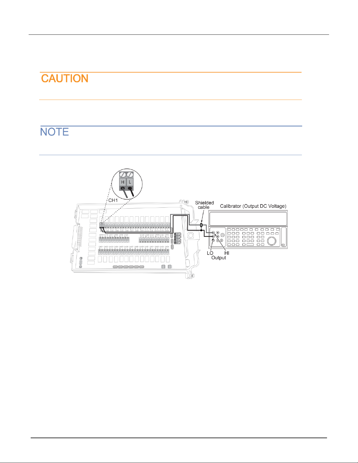
Do not exceed 300 VDC between plug-in module INPUT H and L terminals or between any
adjacent channels. Failure to observe this precaution can cause instrument damage.
To verify DC voltage accuracy:
1. Connect the CH1 H and L INPUT terminals to the DC voltage calibrator as shown in the next figure.
Use shielded, low-thermal connections when testing the 100 mV and 1 V ranges to avoid errors
caused by noise or thermal effects. Connect the shield to the output LO terminal of the calibrator.
2. Install the module in Slot 1 of the DAQ6510.
3. Turn on the power.
4. Allow the instrument to warm up for one hour.
5. Make sure that the front-panel TERMINALS switch is set to REAR.
6. On the front panel of the instrument, select the FUNCTION key and then select DC Voltage.
7. On the Home screen, swipe to the CHANNEL swipe screen.
8. Close channel 101.
9. Set the range to 100 mV.
10. Set the calibrator output to 0.00000 mV DC.
11. Allow the reading to settle.
12. Swipe to the Settings screen.
13. Enable Rel.
14. For the calibrator, source positive, negative, and full-scale voltages, see the ranges listed in the table
below. For each voltage setting, make sure that the reading is within stated limits.
15. Return to the CHANNEL swipe screen and open Channel 1.
Model 7708 Multiplexer Module Instructions for use with DAQ6510
077144500 / April 2018 17
Range
Applied DC voltage
Reading limits (1 year, 18 °C to 28 °C)
100 mV
100.0000 mV
99.9935 to 100.0065 mV
1 V
1.000000 V
0.999969 to 1.000031 V
10 V
10.00000 V
9.99970 to 10.00030 V
100 V
100.0000 V
99.9955 to 100.0045 V
1000 V
300.000 V
299.983 V to 300.017 V
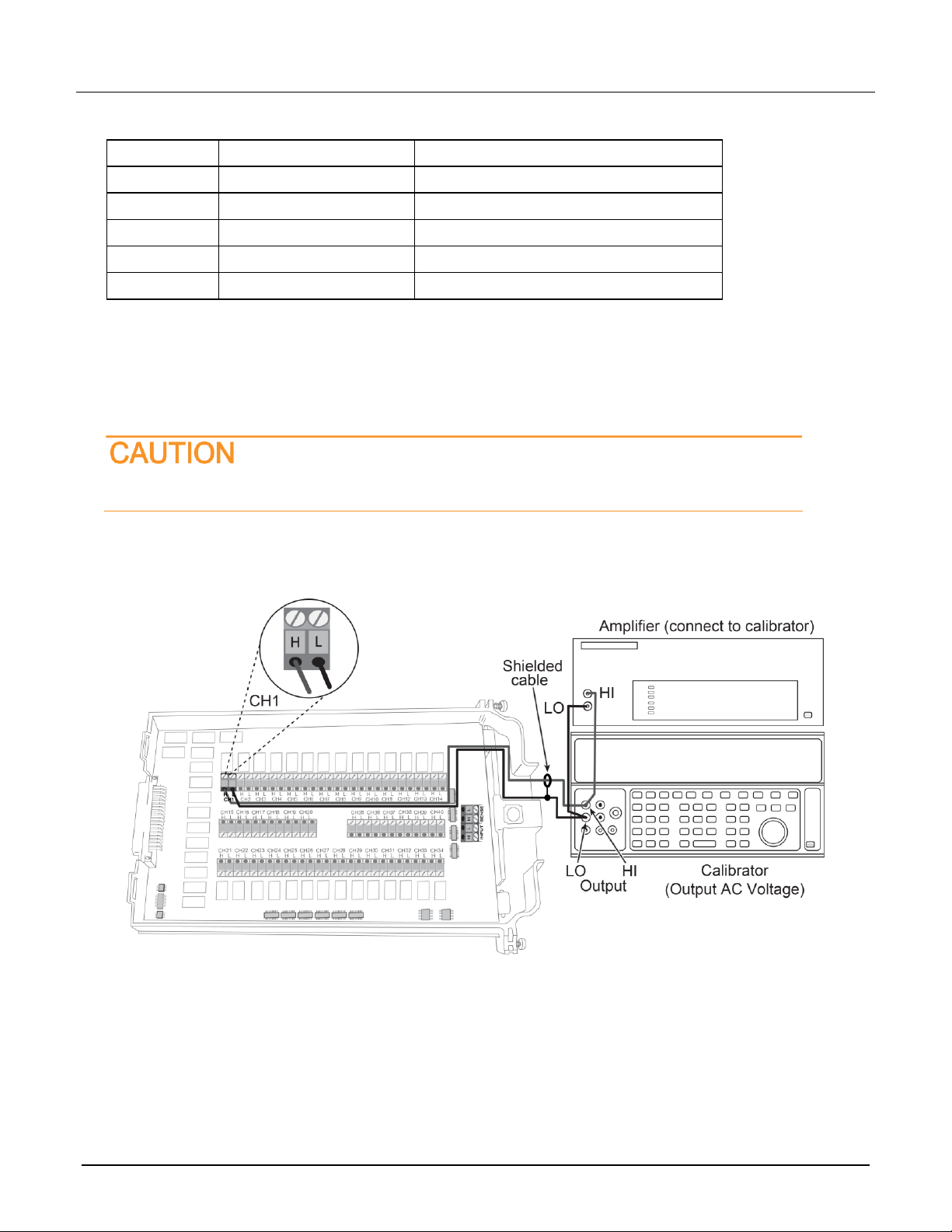
Verifying AC voltage
To check AC voltage accuracy, apply accurate AC voltages at specific frequencies from the AC voltage
calibrator to the module inputs. Verify that the displayed readings fall within specified ranges.
Do not exceed 300 V
RMS
between the INPUT H and L terminals or between adjacent channels,
or 8
10
7
V•Hz input. Failure to observe this precaution may result in instrument damage.
To verify AC voltage accuracy:
1. Connect the CH1 H and L INPUT terminals of the module to the AC voltage calibrator, as shown in the next
figure.