00195642-01_IM-SetupCenter-3.0_EN.pdf - 第16页
System Requirements Device Recognition Unique Machine IDs 16 Installation Manual SIPLACE Setup Center V3.0 Supported Feeder Types 4.5 Device Recognition 4.5.1 Unique Machine IDs Unique machine IDs are attached to all X-S…
System Requirements
Supported Hardware
Installation Manual SIPLACE Setup Center V3.0
15
4.4 Supported Hardware
Supported barcode scanner
Motorola/Symbol MC70 1D/2D barcode scanner together with WLAN Client Module, WLAN Access
Point and Belkin USB LAN-Adapter.
DATALOGIC DRAGON™ M101/D barcode scanner with DRAGON™ OM radio cradle or
DATALOGIC PowerScan® M8300-D barcode scanner (former DRAGON™ M131) with BC-8030
radio cradle
Supported barcode types
Supported machines
Motorola / Symbol MC70 Datalogic Dragon M101/ PowerScan ( M131)
1D Barcode
Codabar
Code 11, Code 39, Code 93, Code 128
D2OF5
EAN-8, EAN-13
I2OF5
RSS-14
RSS Expanded, RSS Limited
UPCA
UPCE0, UPCE1
2D Barcode
Data Matrix
Macro Micro PDF
Macro PDF
Maxi Code
Micro PDF
Micro QR
PDF417
QR Code
EAN 8/EAN 13/128
UPC A/UPC E
Interleaved 2of 5
Code 32, Code 39, Code 128, Code 93, Code 11,
Code 49
MSI / Plessey
Telepen
Codabar, ISSN / ISBN
Standard 2 of 5
ISBT128
Delta IBM
Codablock
Code 16K
Machine Stations software
SIPLACE 80 F4, F4-6, S20; F5, F5 HM, S23 40x.xx
SIPLACE S25 HM, S27 HM, HS50, HS 50+, HS60, HF, HF3 50x.xx
SIPLACE X2, X3, X4; D1, D2, D3, D4 60x.xx
SIIPLACE CF, CS 10x, 40x
SIPLACE X4I 70x.xx
NOTE:
NOTE: The programming system SIPLACE Pro and the Setup Center Station Package can
restrict this range of stations.
System Requirements
Device Recognition Unique Machine IDs
16 Installation Manual SIPLACE Setup Center V3.0
Supported Feeder Types
4.5 Device Recognition
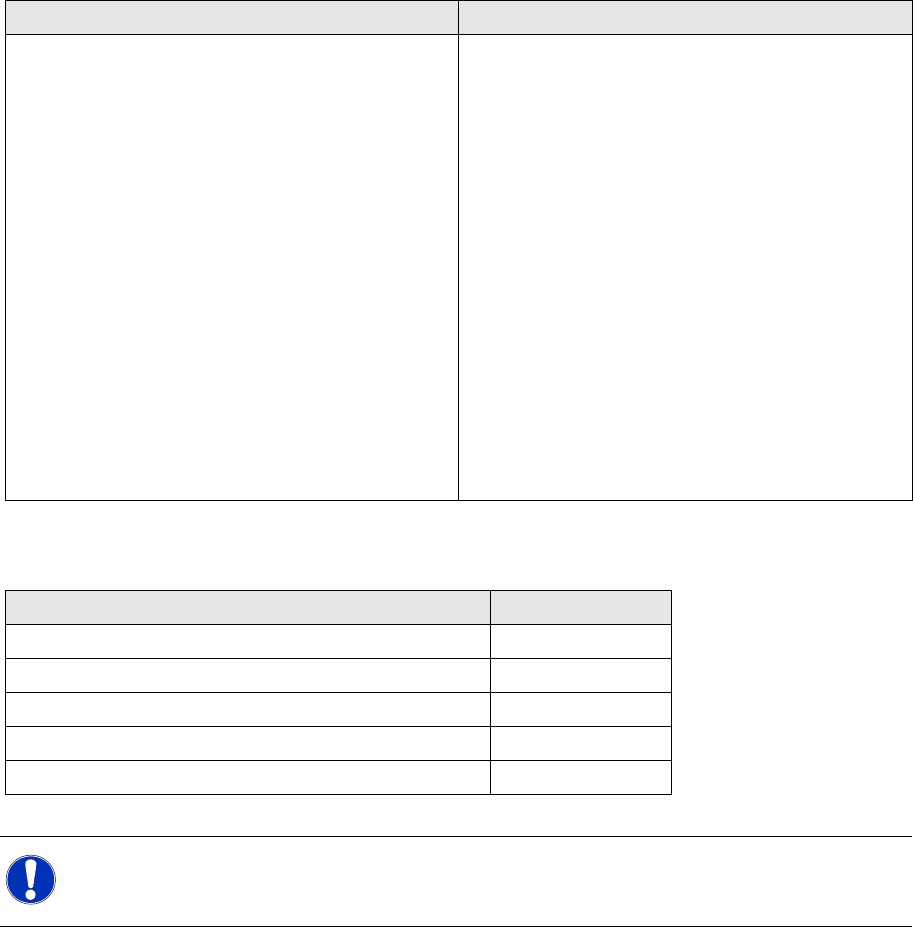
4.5.1 Unique Machine IDs
Unique machine IDs are attached to all X-Series machines ex factory.
For other machine series we recommend you order the unique machine IDs before installation and
attach them to each machine (item no.: 0303470-xx).
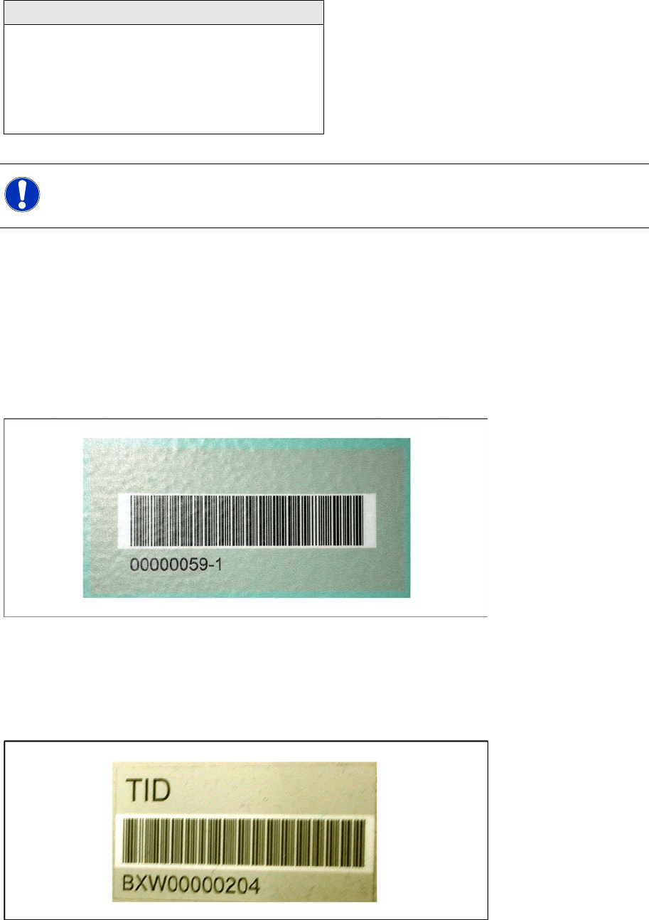
4.5.2 Unique Table ID
Unique table IDs are attached to all X-Series changeover tables ex factory.
For other machine series we recommend you order the unique table IDs before installation and attach
them to each table (item no.: 03046294-xx).
Feeder Types
WPC
MTC 1 & 2
All Tray Loader
All tape feeder types
All Linear feeders
X feeder adapter
NOTE:
NOTE: The programming system SIPLACE Pro and the hardware in use can restrict this range
of feeders.

System components and configurations
Setup Center System components
Installation Manual SIPLACE Setup Center V3.0
17
5 System components and configurations
5.1 System components
5.1.1 Setup Center
A complete installation of SIPLACE Setup Center requires:
SIPLACE Pro Interface and SIPLACE Pro Desk
SIPLACE Setup Center consists of the following components:
SIPLACE Setup Center GUI
SIPLACE Setup Center Database
5.1.2 Scanner system
Dragon / PowerScan Scanner
The Setup Center supports the radio-controlled scanner system "Dragon M101" or "PowerScan M8300-
D (Dragon M131)" by Datalogic. This scanner has a four-line display and supports 1D barcodes only.
Communication between the scanner and the Setup Center requires the cradle "OM-Dragon" or "BC-
8030". This is connected to the Setup Center PC via the serial port. Each Setup Center GUI supports
one cradle. Up to 32 scanners can be linked to one cradle. Setup Center supports simultaneous
operation with multiple scanners.
Motorola / Symbol MC70
The Setup Center supports the 2D barcode scanning with the "Motorola / Symbol MC70" scanner,
equipped with 2D scan engine, usable with 2,4 GHz and 5 GHz WLAN.
2D barcodes contains more information than 1D barcodes. The support for 2D barcode scanners
enables the operator to scan more packaging information at same time.
5.1.3 Forced Setup Verification
The software CD "SIPLACE Setup Center" activates the forced setup verification and the component
level indicator at the SIPLACE placement machine.
The forced setup verification monitors the verification status of individual tracks. Non-verified tracks are
disabled by setup center.
The component level indicator identifies the component fill level for each track, and updates the fill level
for each track at the end of each PCB. Further, it manages threshold values for each track and stops the
pick up process, if a threshold is reached.
5.1.4 Docking Station
The docking station is the link between the X-Series changeover table and the X-Series feeder and forms
the communication point between Setup Center PC and feeders/changeover tables. Docking stations
supply the feeders with compressed air and energy. Data transfer is via a CAN bus cable.
NOTE:
A docking station is required additionally for the pre-setup of X-tables.