YC8_Mainte_E.pdf - 第55页
3-6 3 Periodic maintenance items 2. Monthly inspection This section mainly explains the inspection and cleaning procedures. For details about locations needing lubrication after cleaning, see Chapter 4, "Lubrication…
3-5
3
Periodic maintenance items
1.2.2 Checking the board clamp condition
Check the following points to see the board clamp condition.
1. The board is clamped without play when the board
clamp is raised.
2. There is no clearance between the board and the
board hold plate when the board clamp is raised.
3. The board is flush with the upper surface of the
conveyor rails when the board clamp is raised.
4. The board clamp unit moves smoothly.
53305-N8-00
1.2.3 Checking the board clamp operation
1
Open the [Unit] – [Conveyor] tab.
2
Press the [Width] button to set the
conveyor width.
In the "Target Width" box in the "Conveyor
Width" dialog box that appears, enter the
board width and press [OK].
The conveyor is changed to the width that
was just entered.
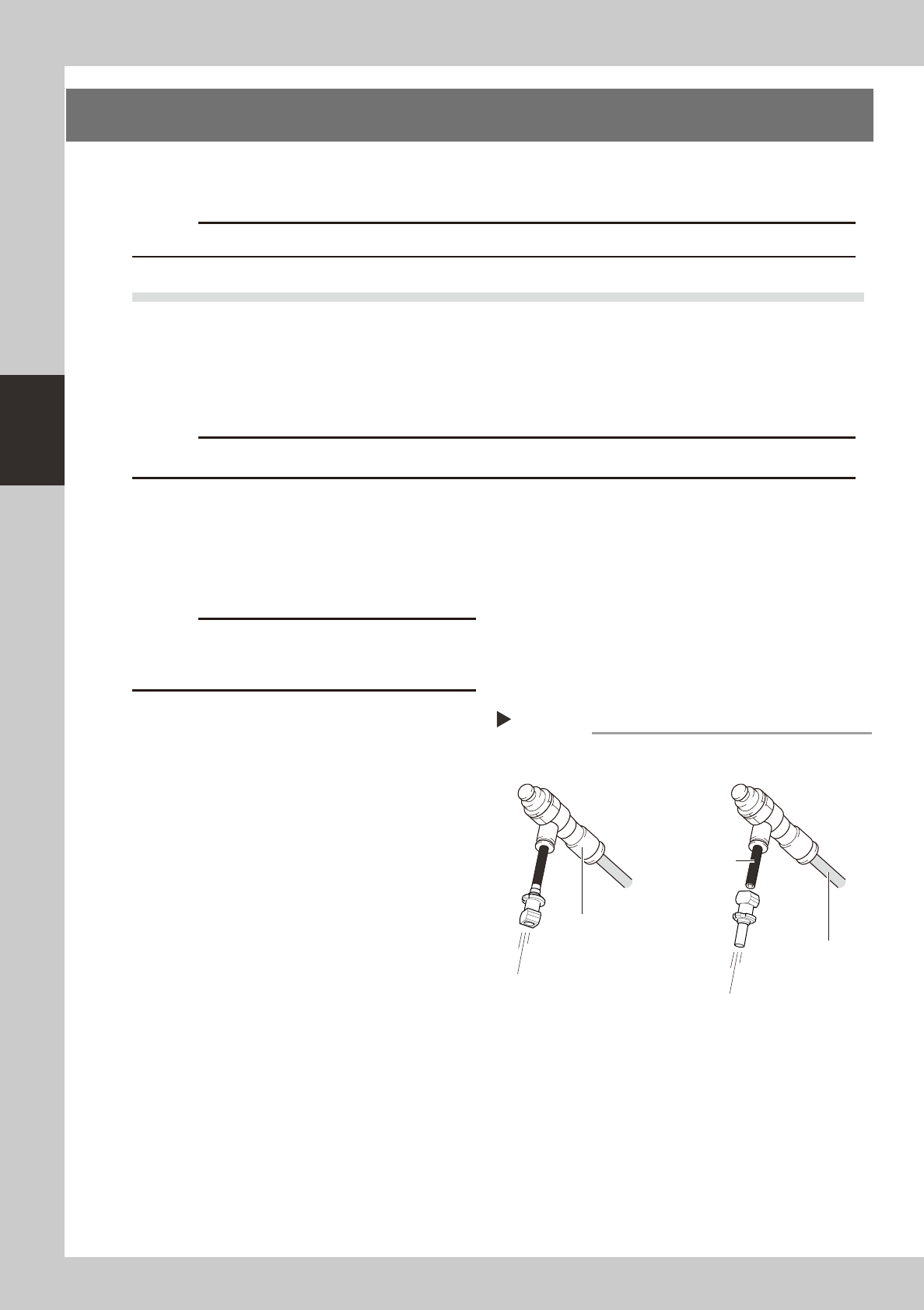
3
Press the [Push Up] button to enter
the board thickness.
In the dialog box that appears, enter the
board thickness and press [OK].
4
Press the [Board Clamp] button to
clamp the board.
5
Press the [Board Clamp] button
again to unclamp the board.
54309-N8-00
Repeat steps 4 and 5 to clamp and unclamp the
board to make sure the clamp unit operates
smoothly.
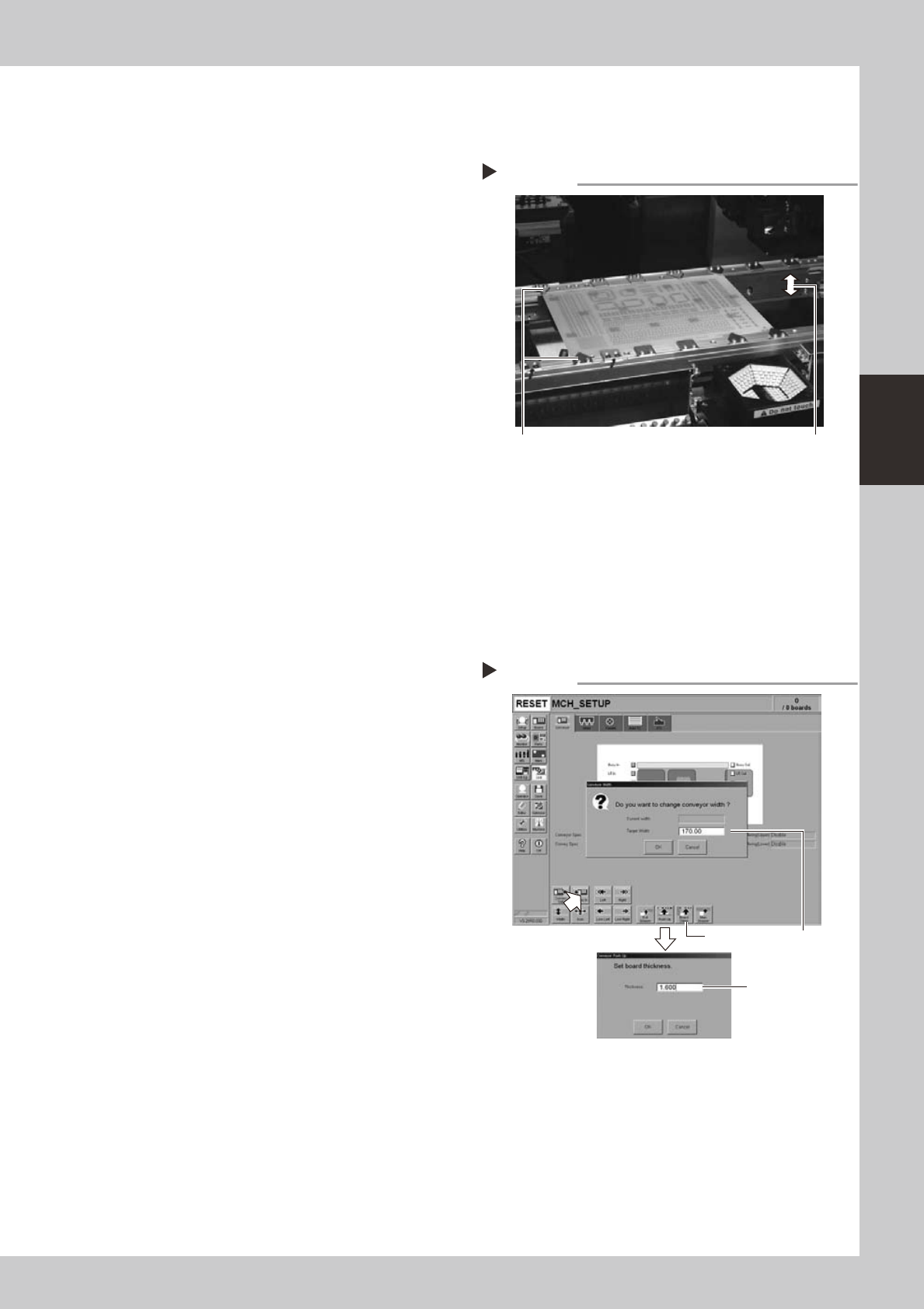
Checking the clamp condition
Check that there is no clearance
between the board and board hold
plate and also that the board is flush
with the conveyor rails.
Clamp and unclamp the
board to check the
movement.
Checking the clamp operation
Step 2-5
Step2Step4, Step5
Step3
3-6
3
Periodic maintenance items
2. Monthly inspection
This section mainly explains the inspection and cleaning procedures. For details about locations needing
lubrication after cleaning, see Chapter 4, "Lubrication points".
c
2.1 Head
2.1.1 Cleaning the nozzle air path
n
Required tools
• Air blow tool (option)
c
e
1
Remove the nozzle from the head.
Always first press the emergency stop button
and then remove the nozzle from the head.
The machine must be in emergency stop to
ensure safety during work.
c
When the machine is equipped with a nozzle station
nozzle station after cleaning.
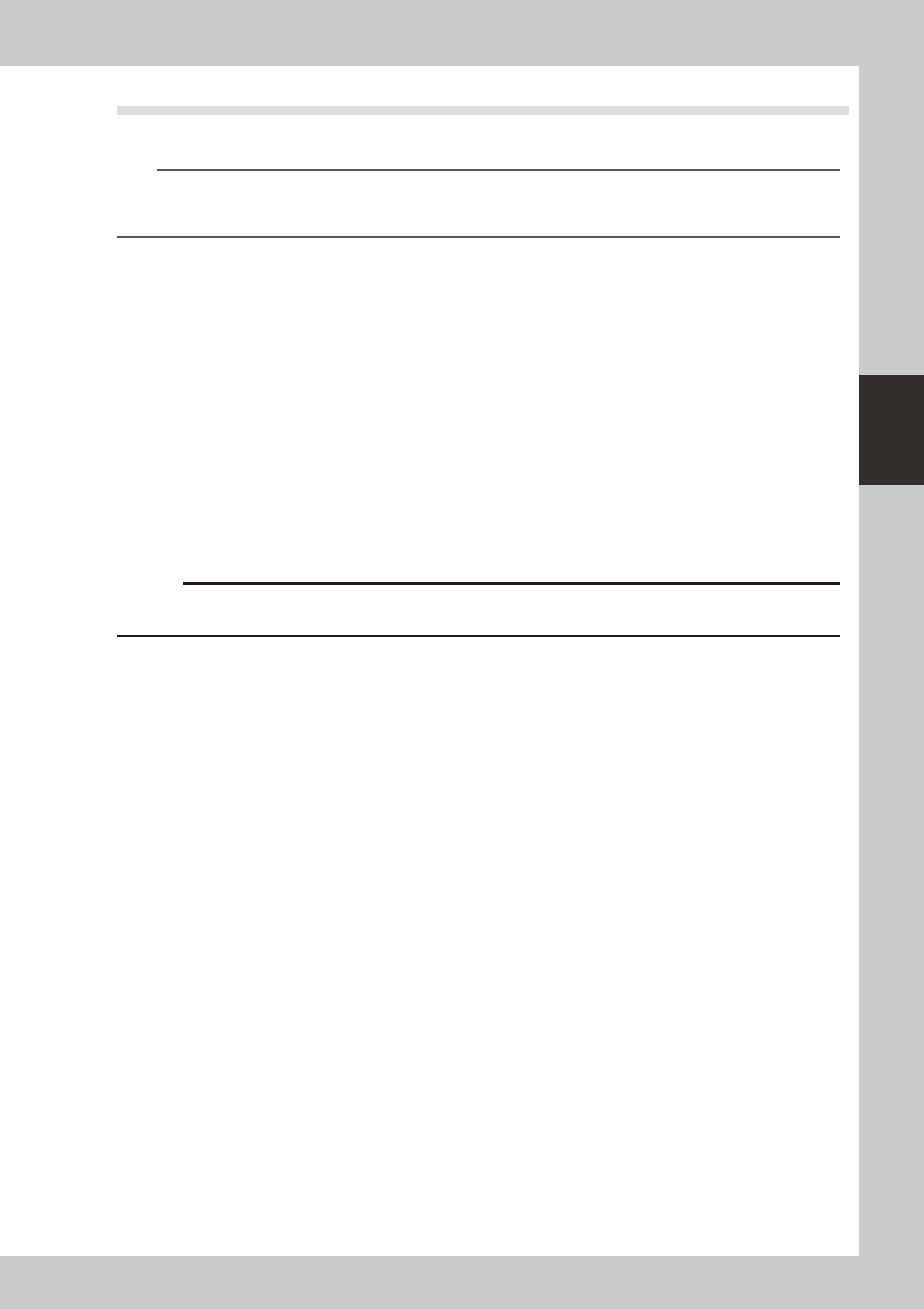
2
Blow air through the nozzle.
Using an air blow tool, blow air through the
nozzle from the nozzle tip and then from the
other end.
53306-N8-00
Air blow
Step 2
Insert the nozzle tip into the air tube
and blow the air.
Air tube (black)
Air blow tool (option)
Air tube (orange)
connected to air supply
port
Blow the air from the nozzle
attachment side.
3-7
3
Periodic maintenance items
2.2 X, Y and W axes
Check the condition of the X, Y, and W axis ball screws and guides, as described below.
n
NOTE
A grease spattering prevention cover is attached to the X-axis and Y-axis. Before starting the inspection work, detach
this grease spattering prevention cover referring to “Detaching grease spattering prevention cover” described later
on.
Checkpoints
1. Any foreign matter adhering to the ball screws and linear guides?
Check if any fallen chips have adhered to the X and Y axis ball screws and/or X, Y and W axis linear guides.
2. Do the ball screws and linear guides have the correct amount of grease?
Check if grease has flowed off or splattered in the air failing to adhere. Also check if grease has discolored or hardened.
3. Any abnormal sounds from the ball screws?
Press the emergency stop button. Then check for any abnormal sounds while pressing the X-axis or Y-axis by hand.
Countermeasures
1. Ball screws and linear guides may be damaged when chips and other material bite into them. If chips are adhering,
wipe them off along with the grease or remove with tweezers, etc.
2. Apply grease while referring “Cleaning and lubrication” described later on.
3. Consult your YAMAHA sales office or representative when abnormal sounds occur even after trying the
countermeasures in the above steps 1 and 2.
c
machine made by the customer is beyond the coverage of the warrantee.