YC8_Mainte_E.pdf - 第86页
5-2 5 How to replace consumable parts 1.2 Replacing the roller lock 1 Remo ve the nozzle arm ASSY . Use a hex wrench to remove the mountin g screws. The leaf springs and nozzle arm ASSY are then removed. c …
5-1
5
How to replace consumable parts
1. Nozzle leaf springs and roller lock
As a result of the inspection stated in section 1.1.3, "Inspecting the nozzle holding force", in Chapter 3, if a
problem is found, it is necessary to replace the nozzle leaf springs or roller lock.
The following describes how to replace the nozzle leaf springs and roller lock.
n
Required tools
• Hex wrench (1.5mm)
• Slotted (flat-blade) screwdriver
• Square cloth
• Replacement parts (See 2.1.1 “Consumable parts and replaceable parts (for repairs)” in Chapter 1.
n
NOTE
Before beginning the work, put a square cloth directly under the head to prevent any parts from being lost or
dropping into other sections and causing trouble.
1.1 Replacing the nozzle leaf springs
e
1
Remove the nozzle.
Press the emergency stop button and
remove the nozzle.
2
Remove the leaf springs.
Use a hex wrench to remove the mounting
screws. The leaf springs and nozzle arm ASSY
are then removed.
n
NOTE
A washer is placed between the mounting screw and
leaf spring. Be careful not to lose it.
53501-N8-00
3
Attach new leaf springs.
Replace the leaf springs with new ones. With
the leaf springs and nozzle arm ASSY kept
pushed upward using a hex wrench,
reattach them.
Be careful not to forget to attach the
washer.
4
Check the attached condition.
1. Check that there is no gap between the
leaf springs and roller.
2. Attempt detaching and attaching the
nozzle several times to check that there
is no looseness.
53502-N8-00
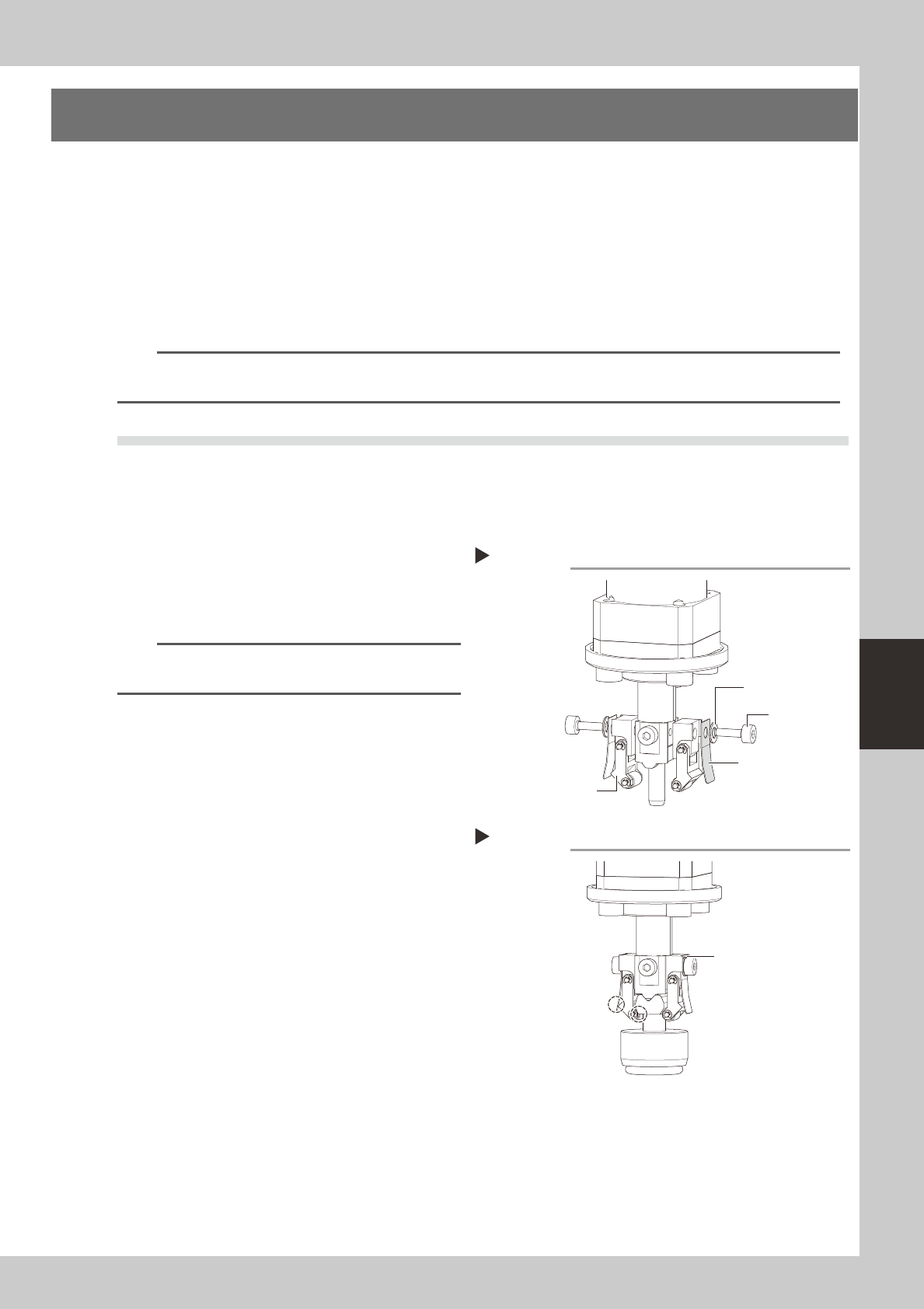
Removing the leaf springs
Step 2
Mounting screw
Leaf spring
Washer
Nozzle arm ASSY
Checking the attached condition
Step 4
Attach with the leaf
springs and nozzle arm
ASSY kept pushed upward.
Check that there is no gap
between the leaf springs
and roller.
5-2
5
How to replace consumable parts
1.2 Replacing the roller lock
1
Remove the nozzle arm ASSY.
Use a hex wrench to remove the mounting
screws. The leaf springs and nozzle arm ASSY
are then removed.
c
53503-N8-00
2
Attach a new nozzle arm ASSY.
Attach the nozzle arm ASSY while pushing
the leaf spring upward with the hex wrench.
Be careful not to forget to attach the
washer.
3
Check the attached condition.
1. Check that there is no gap between the
leaf springs and roller.
2. Attempt detaching and attaching the
nozzle several times to check that there
is no looseness.
n
Replacing only the roller
The following describes how to replace only the roller
after the nozzle arm ASSY has been removed.
1
Remove the circlip.
As shown in the figure on the right, push the
top end of the circlip of the roller with a
slotted screwdriver to remove it.
53504-N8-00
2
Remove the roller.
Pull out the shaft to remove the roller to be
replaced.
3
Attach a new roller.
Insert the shaft into a new roller as shown in
the figure on the right.
53505-N8-00
4
Attach the circlip.
Attach the circlip with a slotted screwdriver
as shown in the figure on the right.
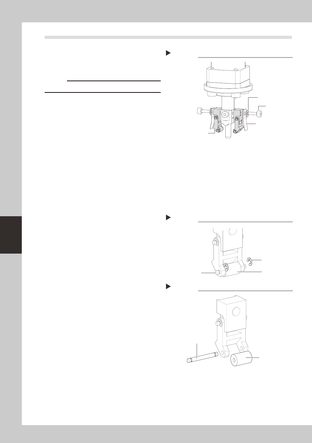
Removing the nozzle arm ASSY
Step 1
Leaf spring
Nozzle arm ASSY
Mounting screw
Washer
Removing the circlip.
Step 1
Shaft
Circlip
Roller
Attaching a new roller
Step 3
Shaft
New roller
5-3
5
How to replace consumable parts
2. Ejector unit
When the function of the ejector bit, solenoid valve or cleaning blow valve has decreased, replace it as
described below. This section describes the replacement procedures, using the V2 head machine as an
example.
2.1 Replacing an ejector bit
n
Required tools
• Precision slotted screwdriver
• Cotton swab stick (option)
• Air blow tool (option)
• Replacement parts (See 2.1.2 “Consumable parts and replaceable parts (for repairs)” in Chapter 1.
• Square cloth
c
1
Make the preparations for the
work.
1. Turn the air supply/shutoff valve inside
the machine lower left panel to the right,
to stop the air supply.
2. Put a square cloth on the conveyor.
3. Move the head to a position where the
work can be made easily.
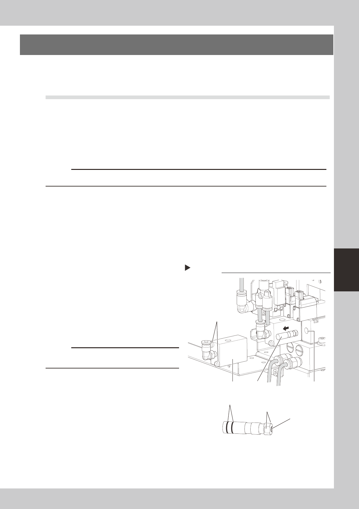
2
Remove the bit.
1. Disconnect the air hose from the air joint
on the block.
2. Use the precision slotted screwdriver to
remove the screws (2 pieces) securing
the block and remove the block.
3. The end of the bit is seen, so pull it out by
hand
53506-N8-00
c
The removed bit cannot be reused. Reuse may cause
component pickup errors.
3
Clean the bit installation hole.
Remove dust or grime in the installation hole
using the air blow tool, lint-free cotton swab,
etc.
4
Install a new bit.
1. Fit an O-ring to the new bit.
2. Insert the bit into the installation hole
while aligning the flat notches on the bit
with the flat sides of the installation hole.
3. Reattach the block in the reverse order
of step 2.
Removing the bit
Step 2
Bit installation hole
Mounting screw (2 pieces)
block
BIT
N BIT
O-ring
Flat notch
O-ring