YC8_Mainte_E.pdf - 第95页
A-3 Appendix 1.3 Connection between machines T o exchange signals such as board request and oper ation status with the downstream or upstream mac hine, the "NEXT INTERF ACE" and "PREVIOUS INTERF A CE"…
A-2
Appendix
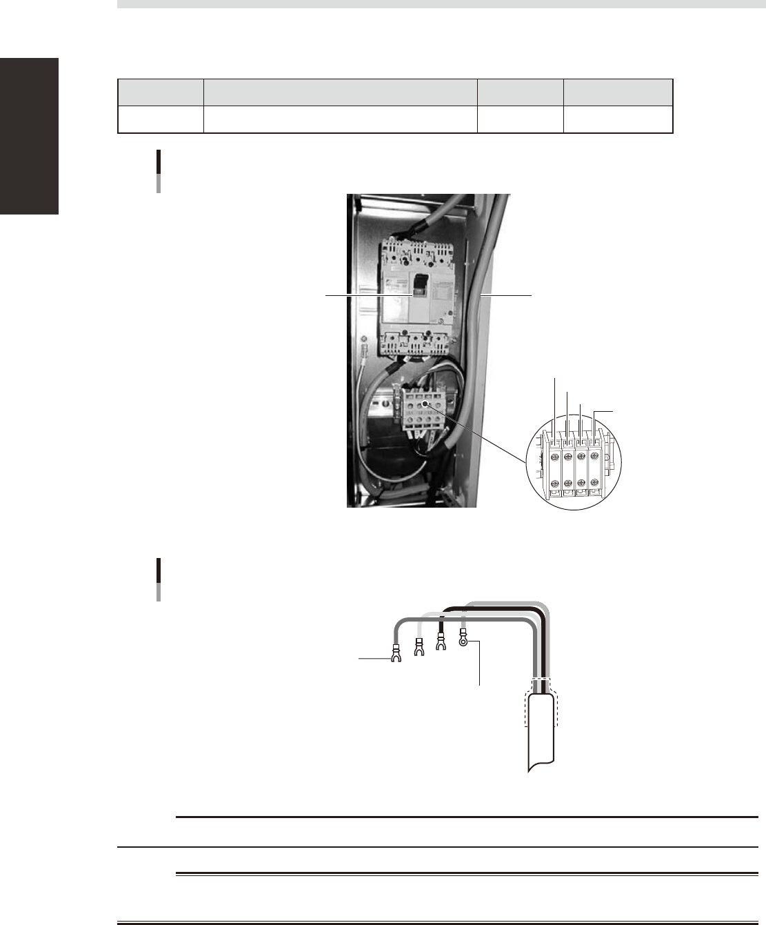
1.2 Power connection terminals
The power connection terminals are located inside the lower right panel on the front of the machine. Connect
the power cable leads as shown below to the L1, L2, L3 and ground terminal (PE) on the power terminal block.
n
Power supply specifications
Model name Power Frequency Power capacity
YC8 3-phase AC 200/208/220/240/380/400/416V (±10%) 50/60Hz 2.2KVA
Power input terminals
Power cable
Power input terminals
L1
L2
L3
PE
Main breaker
53A02-N8-00
Fork-tongue crimp terminal
Fork-tongue crimp terminal
Power cable example
L1
L2
L3
PE
L=100mm
53A03-N8-00
c
Use a power cable whose conductor cross-section area is greater than 2.5mm
2
.
w
WARNING
A-3
Appendix
1.3 Connection between machines
To exchange signals such as board request and operation status with the downstream or upstream machine, the
"NEXT INTERFACE" and "PREVIOUS INTERFACE" connectors located on the rear of the machine are used. The
"NEXT INTERFACE" connector connects to the downstream machine, and the "PREVIOUS INTERFACE"
connector connects to the upstream machine such as a loader. In the case of standard right-to-left flow, the
PREVIOUS INTERFACE connector is located inside the lower right cover on the rear of the machine while the
NEXT INTERFACE connector is located inside the lower left cover on the rear of the machine.
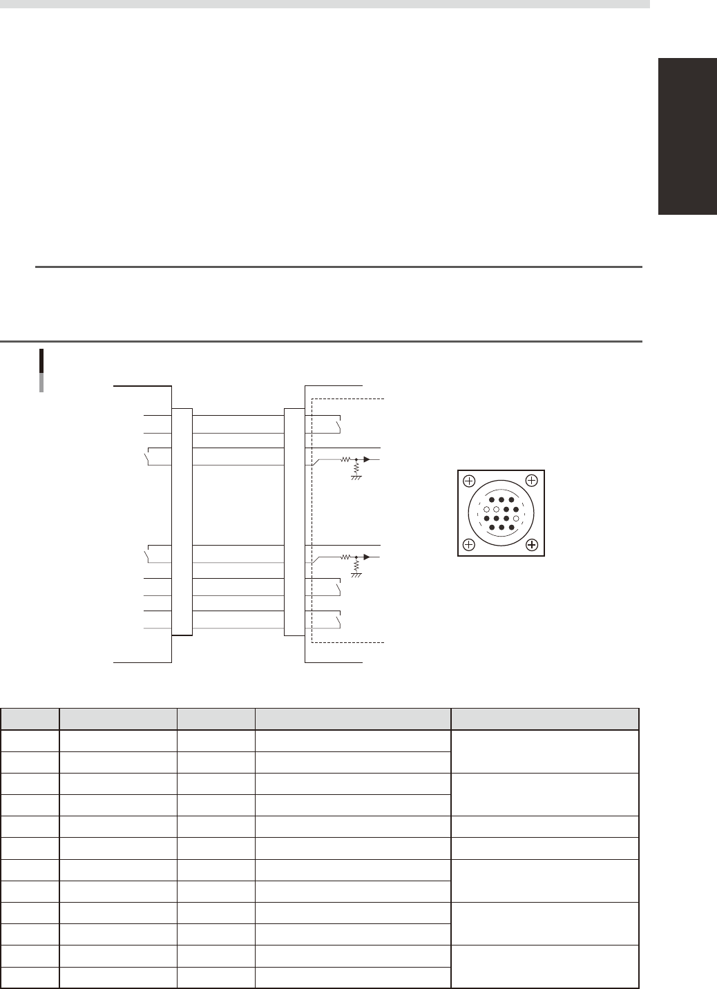
1.3.1 PREVIOUS INTERFACE connector
When the following three conditions are satisfied, the PREVIOUS INTERFACE circuit in the machine allows the
next board to be carried in. (ADVANCED GATE is selected.)
1. Machine is ready for carrying in a board. (BUSY OUT: ON)
2. Board carry-in signal is input from the upstream machine. (BA IN [N01007A1] : ON)
3. Auto operation signal is input from the upstream machine. (UR IN [N01007A3] : ON)
n
NOTE
• When the auto operation running signal (UR IN) from the loader turns off during board carrying-in, the machine
temporarily stops carrying in the board.
• When the board being carried in is detected by the entrance sensor, the BUSY OUT signal turns off.
• Carrying in the board is nished when both the BUSY OUT and BA IN turn off.
1
2
3
4
5
6
7
8
9
10
11
12
13
14
7
12
4
8
1
14
11
3
BUSY OUT
(T01000E4)
+24V
+24V
LR OUT
(T01000E7)
UR IN
(N01007A3)
BA IN
(N01000421)
Carrying-in input
Carry-out request
output
Auto operation running
output
Auto operation running
input
LE OUT
(T0100031)
Waiting for board between
machines input
I/O BOARD
PREVIOUS INTERFACE circuit
PREVIOUS INTERFACE of machineUpstream machine
PREVIOUS INTERFACE
connector
AMP 206043-1
(14-pin receptacle)
53A04-N8-00
n
Board transfer signal specifications (PREVIOUS INTERFACE)
Pin No. Signal name Address I/O specifications Signal specifications
BUSY OUT T01000E4 Relay contact output
Board carrying-in signal output
2 BUSY OUT T01000E4 Relay contact output
3 +24V Input common (+24V)
Board carry-out signal input
4 BA IN N01007A1 Voltage input
5 NC (with dummy pin) (Prevents incorrect insertion.)
6 to 8 NC
9 +24V Input common (+24V)
Auto operation running signal input
10 UR IN N01007A3 Voltage input
11 LR OUT T01000E7 Relay contact output
Auto operation running signal output
12 LR OUT T01000E7 Relay contact output
13 LE OUT T0100031 No-voltage output
Waiting for board between machines
signal input
14 LE OUT T0100031 No-voltage output
A-4
Appendix
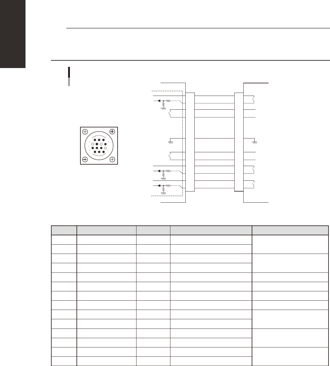
1.3.2 NEXT INTERFACE connector
When the following three conditions are satisfied, the NEXT INTERFACE circuit in the machine allows the
board to be carried out.
1. Machine is ready for carrying out the board. (BA OUT: ON)
2. Board carry-in signal is input from the downstream machine. (BUSY IN [N01007A0] : ON)
3. Auto operation signal is input from the downstream machine. (LR IN [N01007A3] : ON)
n
NOTE
• When the auto operation running signal (LR IN) from the downstream machine turns off during board carrying-out,
the machine temporarily stops carrying out the board.
• When the board being carried out is detected by the exit sensor, the BA OUT signal turns off.
• Carrying out the board is nished when both the BUSY IN and BA OUT turn off.
1
2
3
4
5
6
7
8
9
10
11
12
13
14
BUSY IN
(N01007A0)
+24V
+24V
UR OUT(T01000E6)
LR IN
(N01007A3)
+24V
LE IM
(N01007A4)
BA OUT
(T01000E5)
Carrying-in output
Carry-out request input
Auto operation running
input
Auto operation running
output
Waiting for board between
machines output
I/O BOARD
GND GND
14
11
12
7
4
8
3
1
NEXT INTERFACE circuit
NEXT INTERFACE connector
NEXT INTERFACE of machine
Downstream machine
AMP 206043-1
(14-pin receptacle)
53A05-H0-00
n
Board transfer signal specifications (NEXT INTERFACE)
Part No. Signal name Address I/O specifications Signal specifications
1 +24V Input common (+24V)
Board carrying-in signal input
2 BUSY IN N01007A0 Voltage input
3 BA OUT T01000E5 Relay contact output
Board carry-out request signal
output
4 BA OUT T01000E5 Relay contact output
5 NC
6 NC (with dummy pin) (Prevents incorrect insertion.)
7 GND
8 NC
9 UR OUT T01000E6 Relay contact output
Auto operation running signal
output
10 UR OUT T01000E6 Relay contact output
11 +24V Input common (+24V)
Auto operation running signal
input
12 LR IN N01007A3 Voltage input
13 +24V Input common (+24V)
Waiting for output board between
machines signal input
14 LE IN N01007A4 Voltage input