00900068-02_SM_ASM_ProcessLens_EN.pdf - 第17页
ASM Proces sLens Single - l ane 03/2020 Edit ion 17 3.2 Changing the optical head Ke y: 1) Optica l head Figure 3-1 : Opt i cal head Requirem ent : ● Machine is switche d off . 1. Move the optical h ead car ef ully to th…

ASM ProcessLens Single-lane 03/2020 Edition
16
3 ASM ProcessLens
3.1 Changing the spare parts
3.1.1 List of all spare parts
Spare part Official Description ASMPT part
number
ASM AS part
number
Optical head Vision module 01-D12283 03122959-xx
DLP-module left In-house left DLP module 02-J01731-01 03139342-xx
DLP module right In-house right DLP
module 02-J01731-02 03139345-xx
High ring light High Ringlight board 03-29089 03122924-xx
Low ring light Low Ringlight board 03-29090 03122925-xx
Encoder reader X X encoder assy 03157187-xx
Encoder reader Y Y Gantry Left Encoder
Assy
03157188-xx
Y Gantry Right Encoder
Assy
03157190-xx
Encoder reader Z Z axis encoder 03157180-xx
Y scale bar Y scale assembly 01-D12593 03139293-xx
X scale bar X scale assembly 01-D12541 03139296-xx
Conveyor belt Brecoflex timing belt
10T5/2440 73-00849 03139303-xx
Conveyor motor BLM-6080-24 motor 03110463-xx
Width adjustment belt WA brecoflex timing belt
10T5/1700 73-S03106079-01 03106079-xx
TSP400 Conveyor controller TSP-
400 CPL 05-S03060811-06 03060811-xx
Motor for width adjustment BLM-4280-24 motor 03106082-xx
Motor for lifting table BLDS motor with PLG
and brake 05-S03064983-01 03064983-xx
Input sensor SPI conveyor input area
SNR cable 02-92412 03122931-xx
Sonar sensor Conveyor sonar sensor
cable 12-F10307 03122932-xx
Stopper E-series conveyor
stopper unit - 03106565-xx
Output sensor SPI conveyor output area
SNR cable 02-92414 03122933-xx
Table 3-1: List of spare parts
ASM ProcessLens Single-lane 03/2020 Edition
17
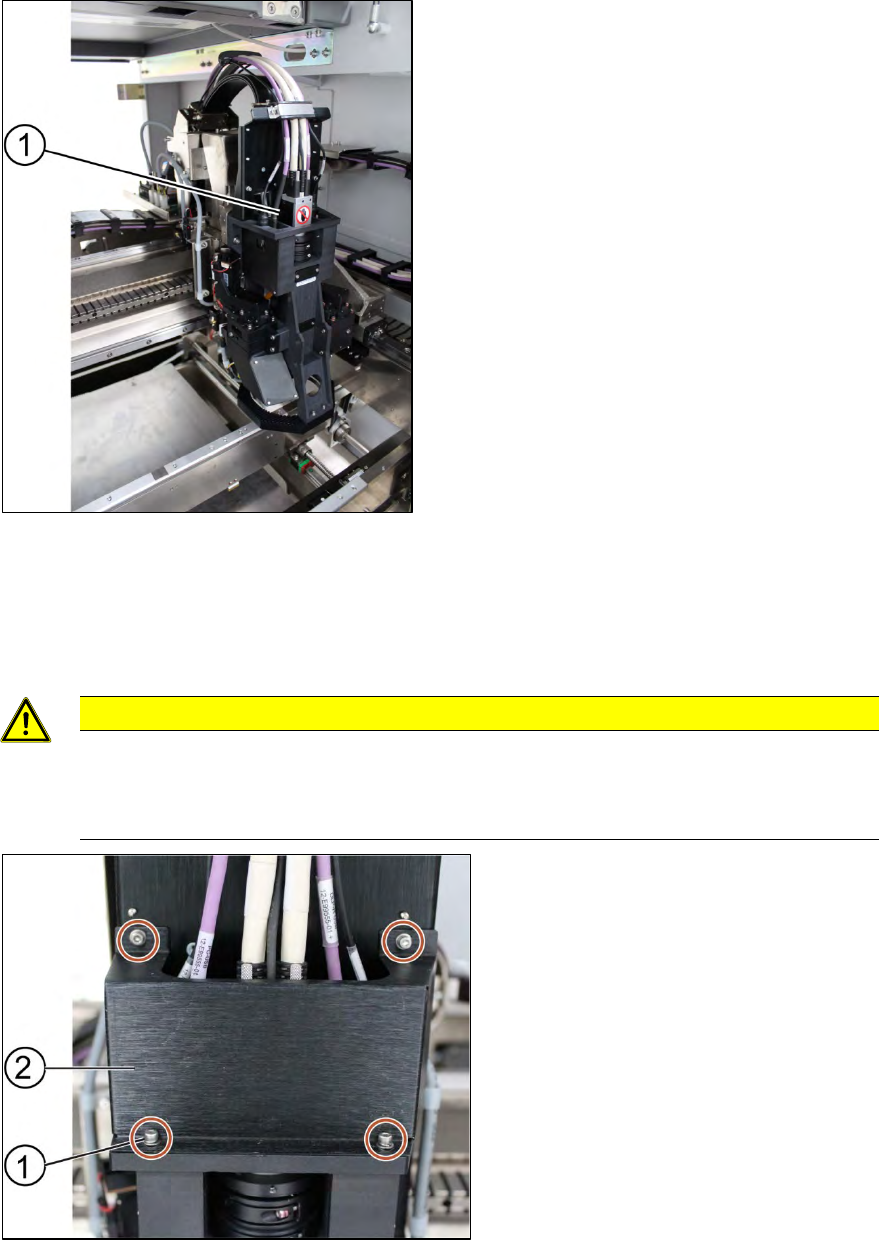
3.2 Changing the optical head
Key:
1) Optical head
Figure 3-1: Optical head
Requirement:
● Machine is switched off.
1. Move the optical head carefully to the middle of the machine.
CAUTION
Sensitive camera system
The camera system is very sensitive and must therefore not be touched.
Make sure you don’t touch the camera when moving the gantry.
Key:
1) Screws (4 x)
2) Cover
Figure 3-2: Cover for cables
2. Remove the cover that protects the connection spots for the cables by unscrewing the screws
(1) by using an Allen key size 2.5.
ASM ProcessLens Single-lane 03/2020 Edition
18
3. Place the dismantled cover on a service table.
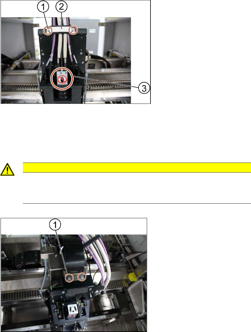
Key:
1) Screw (2 x)
2) Cable clamp
3) Camera system
Figure 3-3:Cable clamp
4. Remove the cable clamp (2) that fixes the cables by unscrewing the screws (1) using an Allen
key size 2.5.
5. Place the dismantled cable clamp (2) on a service table.
6. Unplug the cables.
CAUTION
Sensitive camera system.
The camera system is very sensitive.
Therefore do not touch the camera system to avoid damage to it.
7. Carefully put the cables aside.
Key:
1) Screw (2 x)
Figure 3-4: Optical head
8. Unscrew the screws (1) mounted on top of the optical head fixing the ribbon cable connectors
using an Allen key size 2.5.
9. Remove the ribbon cable connectors out of the sockets by pulling the clamps apart.