00900068-02_SM_ASM_ProcessLens_EN.pdf - 第20页
ASM Proces sLens Single - l ane 03/2020 Edit ion 20 3.3 Changing the low Ring li ght assembly Ke y: 1) Low Rin glight as sem bly Figure 3-6 : L ow Ringlight assembly Require ment: ● Machine is switc hed off . ● Use a T s…
ASM ProcessLens Single-lane 03/2020 Edition
19
Key:
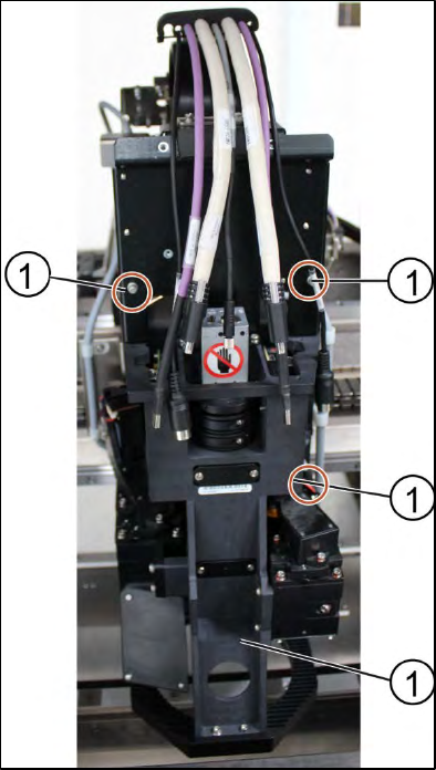
1) Screw (4 x)
Figure 3-5: Optical head
10. Unscrew the screws (1) fixing the optical head at the machine using an Allen key size 2.5. Start
from the bottom.
11. Carefully unscrew all screws. Make sure you don’t drop the optical head.
Installation
Follow the removal instructions in reverse order for installation.
3.2.1 Check the calibration of the optical head
When the optical head is removed from the machine the optical head needs to be calibrated again.
Refer to chapter "4 Machine - Calibrations".
ASM ProcessLens Single-lane 03/2020 Edition
20
3.3 Changing the low Ringlight assembly
Key:
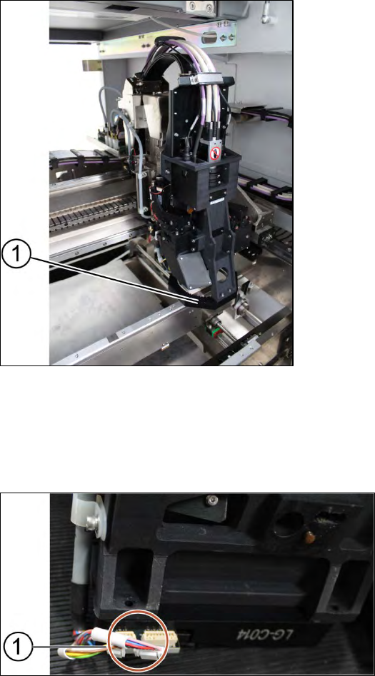
1) Low Ringlight assembly
Figure 3-6: Low Ringlight assembly
Requirement:
● Machine is switched off.
● Use a T shaped Allen key to carry out this job.
Key:
1) Connectors
Figure 3-7: Connectors at low Ringlight assembly
1. Unplug the connectors (1) at the back of the low Ringlight assembly.
ASM ProcessLens Single-lane 03/2020 Edition
21
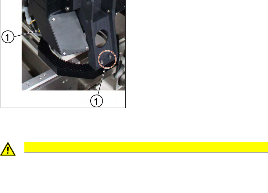
Key:
1) Screw (4 x)
Figure 3-8: Low Ringlight assembly
2. Remove the screws (1) on the low Ringlight assembly using an Allen key size 2.5.
CAUTION
Different types of screws
There are two different types of screws. The ones in the back are shorter than the ones
in the front.
Do not interchange the screws.
3. Remove the low Ringlight assembly and place it on a service table.
Installation
Follow the removal instructions in reverse order for installation.