00900068-02_SM_ASM_ProcessLens_EN.pdf - 第21页
ASM Proces sLens Single - l ane 03/2020 Edit ion 21 Ke y: 1) Screw (4 x) Figure 3-8 : L ow Ringlight assembly 2. Rem ove the scre ws (1) on t he lo w R inglight assem bly us ing an Al len k ey size 2.5. C AU T I O N Diff…
ASM ProcessLens Single-lane 03/2020 Edition
20
3.3 Changing the low Ringlight assembly
Key:
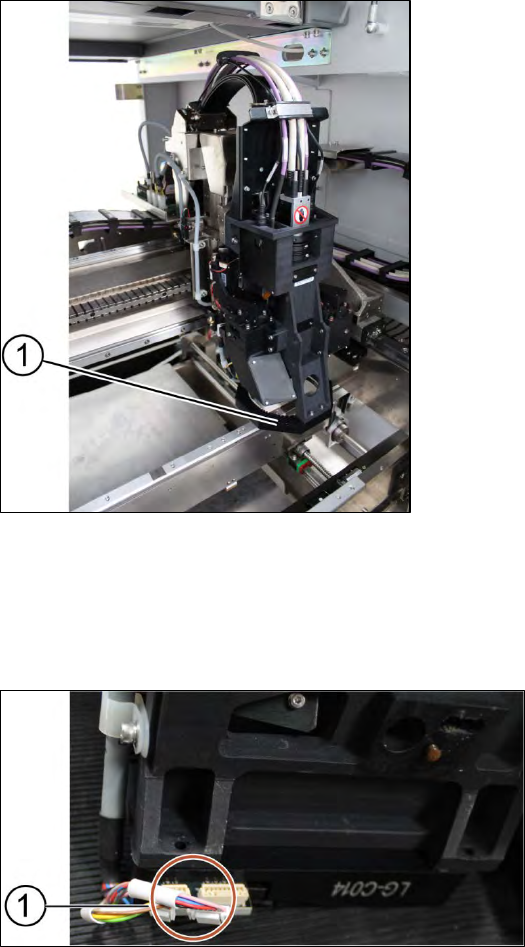
1) Low Ringlight assembly
Figure 3-6: Low Ringlight assembly
Requirement:
● Machine is switched off.
● Use a T shaped Allen key to carry out this job.
Key:
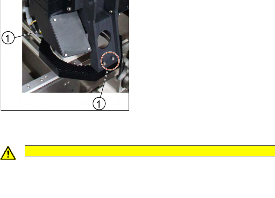
1) Connectors
Figure 3-7: Connectors at low Ringlight assembly
1. Unplug the connectors (1) at the back of the low Ringlight assembly.
ASM ProcessLens Single-lane 03/2020 Edition
21
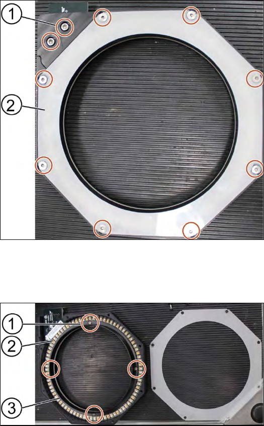
Key:
1) Screw (4 x)
Figure 3-8: Low Ringlight assembly
2. Remove the screws (1) on the low Ringlight assembly using an Allen key size 2.5.
CAUTION
Different types of screws
There are two different types of screws. The ones in the back are shorter than the ones
in the front.
Do not interchange the screws.
3. Remove the low Ringlight assembly and place it on a service table.
Installation
Follow the removal instructions in reverse order for installation.
ASM ProcessLens Single-lane 03/2020 Edition
22
3.3.1 Change the low Ringlight board
Requirement:
● Low Ringlight assembly is dismantled.
Key:
1) Screw (10 x)
2) Cover
Figure 3-9: Low Ringlight assembly
1. Unscrew all screws (1) with an Allen key size 2.5.
2. Remove the cover (2) of the low Ringlight assembly
Key:
1) Screw (4 x)
2) Low Ringlight board
3) Plastic ring
Figure 3-10: Low Ringlight assembly (dismantled)
3. Unscrew the screws (1) using a Philips screwdriver.
4. Remove the plastic ring (3) and place it on the service table.
5. Change the low Ringlight board (2).
Installation
Follow the removal instructions in reverse order for installation.