00900068-02_SM_ASM_ProcessLens_EN.pdf - 第25页
ASM Proces sLens Single - l ane 03/2020 Edit ion 25 C AU T I O N Screws of the Ringl ight boar d W hen the high Ri nglight b oard is r eassem bled, one must not overtig hten th e screws, as this m ay damage th e high Rin…

ASM ProcessLens Single-lane 03/2020 Edition
24
3.4.1 Change the high Ringlight board
Requirement:
● High Ringlight assembly is dismantled.
Key:
1) Connector
2) Screw (4 x) and washers
(4 x)
Figure 3-12: High Ringlight assembly (dismantled)
1. Unscrew the screws (1) using an Allen key size 1.5.
2. Separate the high Ringlight assembly.
CAUTION
Ringlight assembly
The two parts of the Ringlight assembly are hold together by two dowel pins. When
separating the two parts the Ringlight assembly may get damaged.
To separate the two parts, carefully pull the parts apart.
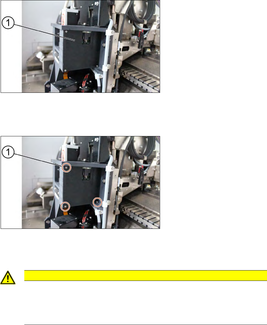
Key:
1) High Ringlight assembly
2) Dowel pin
3) High Ringlight board
4) Screw (6 x)
Figure 3-13: High Ringlight assembly (dismantled)
3. Unscrew the screws (4) that hold the high Ringlight board (3) in place using a Philips
screwdriver.
4. Remove the high Ringlight board (3).
Installation
Follow the removal instructions in reverse order for installation. Also observe the following
instructions:
ASM ProcessLens Single-lane 03/2020 Edition
25
CAUTION
Screws of the Ringlight board
When the high Ringlight board is reassembled, one must not overtighten the screws, as
this may damage the high Ringlight board.
Do not overtighten the screws (4).
3.4.2 Check the function of the low ring light and the high ring light
Requirement:
● Machine is switched on.
● Machine doors are open.
● The low ring light and the high ring light are mounted.
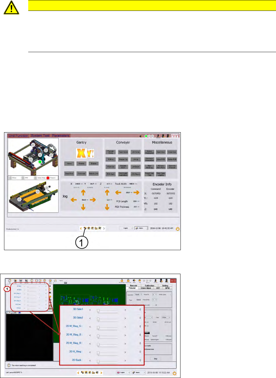
Key:
1) Control button
Figure 3-14: Diagnostic page
1. Go to the diagnostic pages and press the control button.
Key:
1) Lighting control button
Figure 3-15: Lighting control page
2. Start with M-Ring_G to check the green light of the low ring light.
3. Check if all LEDs are function and flashing by using a mirror or view from underneath the
optical head.
4. Approach the same for all other slider bars under 2D lightings bar.
ASM ProcessLens Single-lane 03/2020 Edition
26
3.5 Change the DLP left and right controller
Key:
1) Right DLP module
Figure 3-16: DLP modules
Requirement:
● Machine is switched off.
Key:
1) Screw (3 x)
Figure 3-17: Cover for DLP module
1. Unscrew the screws (1) using a Philips screwdriver to remove the cover of the DLP module
(circuit board)
CAUTION
Small screws
The screws are very small. When the screws fall into the machine they may damage it.
Make sure the screws don’t fall into the machine.
Make sure no screw is left behind inside the machine.