00900068-02_SM_ASM_ProcessLens_EN.pdf - 第26页
ASM Proces sLens Single - l ane 03/2020 Edit ion 26 3.5 Change the DLP left and ri ght controll er Ke y: 1) Right D LP m odule Figure 3- 16 : DLP modules Require ment: ● Machine is switche d off . Ke y: 1) Screw (3 x) Fi…
ASM ProcessLens Single-lane 03/2020 Edition
25
CAUTION
Screws of the Ringlight board
When the high Ringlight board is reassembled, one must not overtighten the screws, as
this may damage the high Ringlight board.
Do not overtighten the screws (4).
3.4.2 Check the function of the low ring light and the high ring light
Requirement:
● Machine is switched on.
● Machine doors are open.
● The low ring light and the high ring light are mounted.
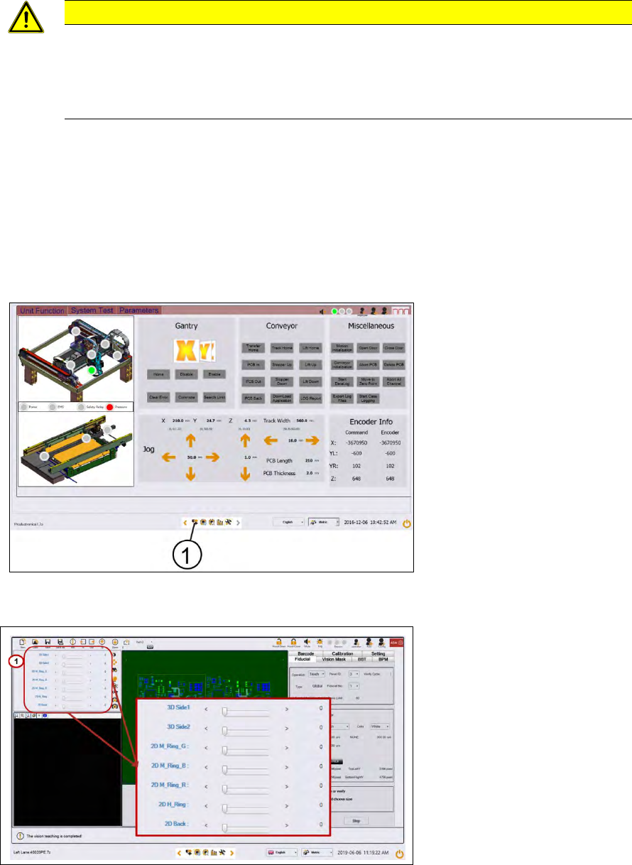
Key:
1) Control button
Figure 3-14: Diagnostic page
1. Go to the diagnostic pages and press the control button.
Key:
1) Lighting control button
Figure 3-15: Lighting control page
2. Start with M-Ring_G to check the green light of the low ring light.
3. Check if all LEDs are function and flashing by using a mirror or view from underneath the
optical head.
4. Approach the same for all other slider bars under 2D lightings bar.
ASM ProcessLens Single-lane 03/2020 Edition
26
3.5 Change the DLP left and right controller
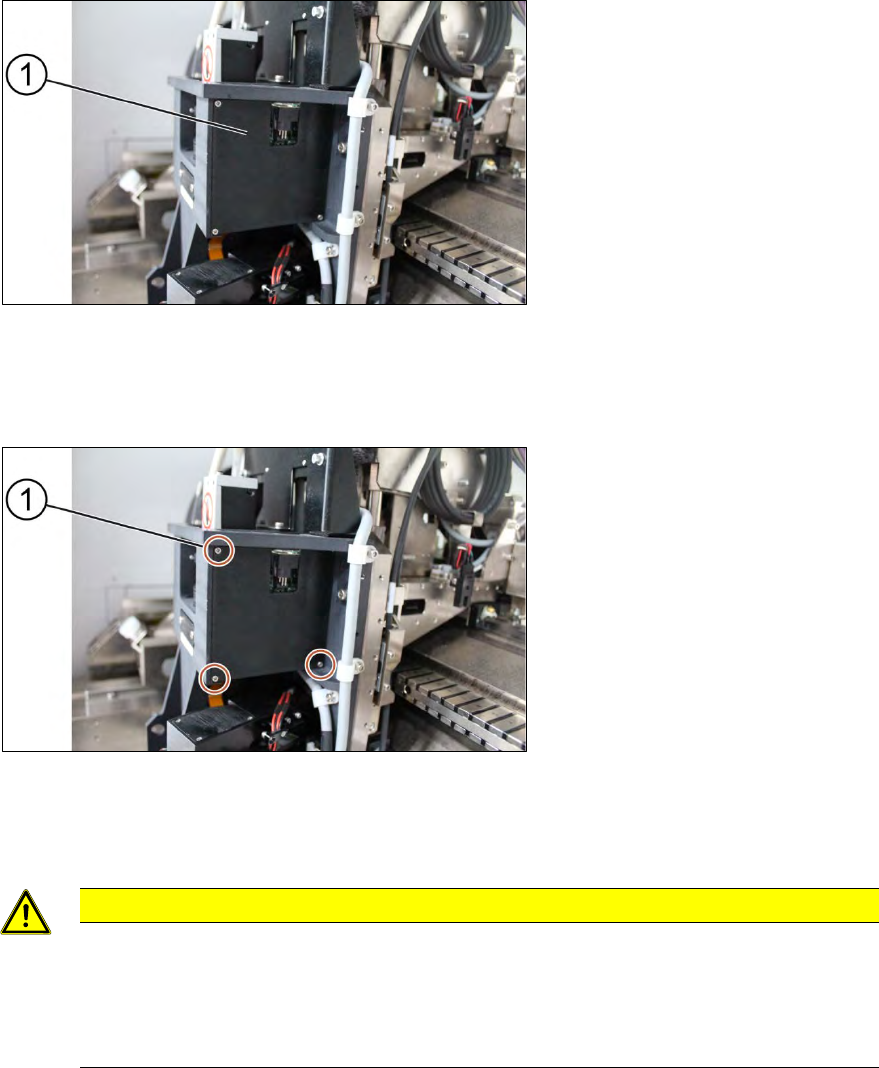
Key:
1) Right DLP module
Figure 3-16: DLP modules
Requirement:
● Machine is switched off.
Key:
1) Screw (3 x)
Figure 3-17: Cover for DLP module
1. Unscrew the screws (1) using a Philips screwdriver to remove the cover of the DLP module
(circuit board)
CAUTION
Small screws
The screws are very small. When the screws fall into the machine they may damage it.
Make sure the screws don’t fall into the machine.
Make sure no screw is left behind inside the machine.
ASM ProcessLens Single-lane 03/2020 Edition
27
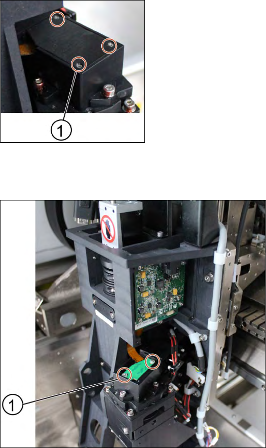
Key:
1) Screw (3 x)
Figure 3-18: Cover for DMD module
2. Unscrew the screws (1) using a Philips screwdriver to remove the cover of the DMD module
(connector).
Key:
1) Screw (2 x)
Figure 3-19: DMD module
3. Unscrew the screws (1) that connect the connector with the DMD module by using an Allen key
size 1.5.
4. Carefully lift the connector of DMD module.