00900068-02_SM_ASM_ProcessLens_EN.pdf - 第27页
ASM Proces sLens Single - l ane 03/2020 Edit ion 27 Ke y: 1) Screw (3 x) Figure 3- 18 : Cover for DMD module 2. Unscrew t he screws (1) using a Philips s crewdri ver to rem ove the cover of the D MD m odule (connector ).…
ASM ProcessLens Single-lane 03/2020 Edition
26
3.5 Change the DLP left and right controller
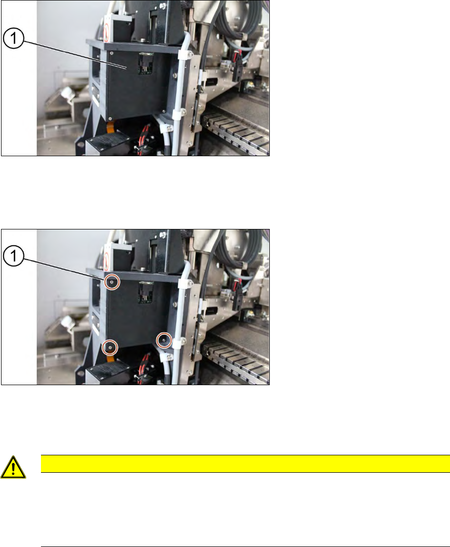
Key:
1) Right DLP module
Figure 3-16: DLP modules
Requirement:
● Machine is switched off.
Key:
1) Screw (3 x)
Figure 3-17: Cover for DLP module
1. Unscrew the screws (1) using a Philips screwdriver to remove the cover of the DLP module
(circuit board)
CAUTION
Small screws
The screws are very small. When the screws fall into the machine they may damage it.
Make sure the screws don’t fall into the machine.
Make sure no screw is left behind inside the machine.
ASM ProcessLens Single-lane 03/2020 Edition
27
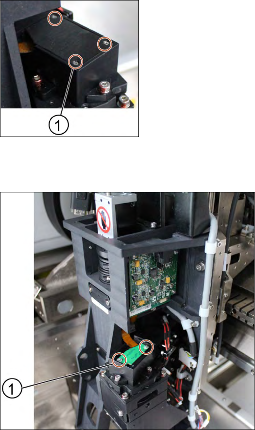
Key:
1) Screw (3 x)
Figure 3-18: Cover for DMD module
2. Unscrew the screws (1) using a Philips screwdriver to remove the cover of the DMD module
(connector).
Key:
1) Screw (2 x)
Figure 3-19: DMD module
3. Unscrew the screws (1) that connect the connector with the DMD module by using an Allen key
size 1.5.
4. Carefully lift the connector of DMD module.
ASM ProcessLens Single-lane 03/2020 Edition
28
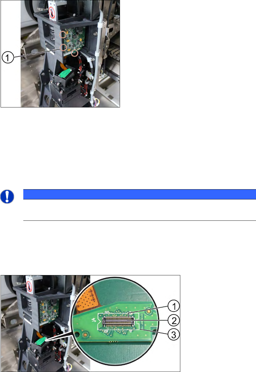
Key:
1) Screw (3 x)
Figure 3-20: DLP module
5. Unscrew the screws (1) of the DLP module by using an Allen key size 2.0.
6. Remove the circuit board and replace it.
7. The steps for the left and the right module are identical.
Installation
Follow the removal instructions in reverse order for installation.
NOTICE
Modules aren’t interchangeable
Be aware that the two modules are not interchangeable.
3.5.1 Replacing the DLP module
Requirement:
● DLP module is dismantled.
Key:
1) Pin
2) Connector
3) DLP interface board to
DMD
Figure 3-21: Connector of DLP module
1. Put the DLP module in its position.
2. Make sure that the connector is in the right position and doesn’t bend the pin. Use an external
light to check that the holes of the connector and the drilling holes for the screws are in line.