00900068-02_SM_ASM_ProcessLens_EN.pdf - 第35页
ASM Proces sLens Single - l ane 03/2020 Edit ion 35 3.11 Check the alignment of the x, y and z encoder re ader Furtherm ore the a lignm ent of the x , y and z readers need to be chec ked when ever the re aders or the sca…
ASM ProcessLens Single-lane 03/2020 Edition
34
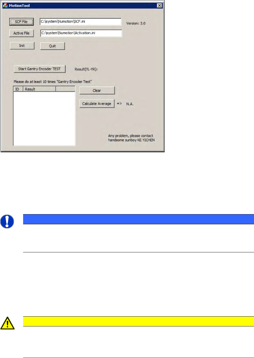
Figure 3-31: Gantry Index ParallelTool
2. Start the Process "Gantry Index ParallelTool"
3. Press the Init button to initialize the gantry.
4. Press the "Start Gantry encoder TEST" button.
5. Slowly push the gantry backwards.
NOTICE
Test results
This needs to be done within 5 seconds after the button has been pushed. Otherwise the
measuring will not take place.
6. Press the "Stop the Gantry Encoder" button.
7. Repeat this at least 10 x times.
8. The specified range is +/- 1000.
9. If any of the 10 X results differ from the specified range go back to adjust the brackets and
repeat the check.
CAUTION
Installed flexures
Installed flexures cause damage to the machine when in operation mode,
Remove flexures at the end of the alignment test.
ASM ProcessLens Single-lane 03/2020 Edition
35
3.11 Check the alignment of the x, y and z encoder reader
Furthermore the alignment of the x, y and z readers need to be checked whenever the readers or
the scale bar has been changed.
Requirement:
● Machine is switched on.
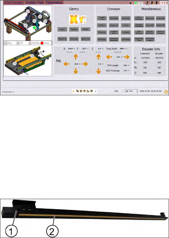
Figure 3-32: Diagnostic page
1. Go to the diagnostic page.
2. Click on the tab "Unit function".
3. Go to the section "Gantry".
4. Select the X button and click on the "Home" button.
5. Approach the same for the y and z readers.
3.12 Changing the Y scale bars
Key:
1) Y scale bar
2) Scale
Figure 3-33: Y scale bar
Requirement:
● Machine is switched off.
ASM ProcessLens Single-lane 03/2020 Edition
36
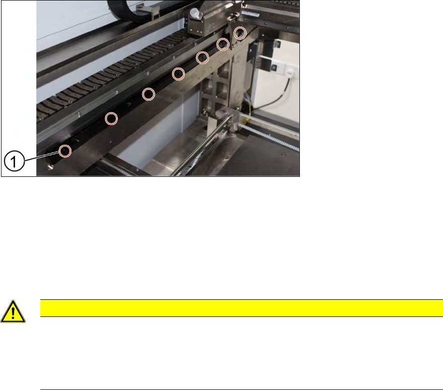
Key:
1) Screw (7 x)
Figure 3-34: Y scale bar
1. Unscrew the screws (1) off the scale bar using an T shaped Allen key size 2.5.
2. Carefully pull out the scale bar.
3. Do not damage the encoder reader. The sensitive reader may be protected by using a piece of
paper.
4. Put in the new scale bar.
CAUTION
The surface of the scale bars
Fingerprints or scratches damage the scale bars which then need to be exchanged.
Do not touch or scratch the surface of the scale bars.
Be careful when pulling out the reader and when putting it back again.
Installation
1. Tighten the screws (1).
2. Check the space between the reader and the scale bar by using the 2.1 mm spacer provided.
3. Check the lights of the encoder at the back of the machine.
4. Slowly move the gantry backwards and forwards. See section 3.9 Color code for the encoder
readers.
5. Adjust the brackets when the lights indicate to do so.
6. The steps to change the other scale bar are identical.
7. Check the alignment of the y scale bar. Go to section 3.10 Check the alignment of the encoder
reader of the Y gantry and section 3.11 Check the alignment of the x, y and z encoder reader.