00900068-02_SM_ASM_ProcessLens_EN.pdf - 第37页
ASM Proces sLens Single - l ane 03/2020 Edit ion 37 3.13 Changing the conve yor belt Require ment: ● Machine is switche d off . ● Tension m eter . Ke y: 1) Screw (1 x) 2) Belt 3) Rod Figure 3- 35 : Gear and conveyor rod …
ASM ProcessLens Single-lane 03/2020 Edition
36
Key:
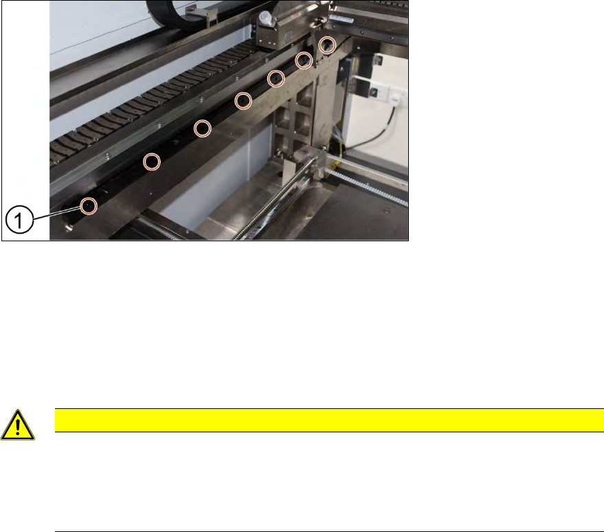
1) Screw (7 x)
Figure 3-34: Y scale bar
1. Unscrew the screws (1) off the scale bar using an T shaped Allen key size 2.5.
2. Carefully pull out the scale bar.
3. Do not damage the encoder reader. The sensitive reader may be protected by using a piece of
paper.
4. Put in the new scale bar.
CAUTION
The surface of the scale bars
Fingerprints or scratches damage the scale bars which then need to be exchanged.
Do not touch or scratch the surface of the scale bars.
Be careful when pulling out the reader and when putting it back again.
Installation
1. Tighten the screws (1).
2. Check the space between the reader and the scale bar by using the 2.1 mm spacer provided.
3. Check the lights of the encoder at the back of the machine.
4. Slowly move the gantry backwards and forwards. See section 3.9 Color code for the encoder
readers.
5. Adjust the brackets when the lights indicate to do so.
6. The steps to change the other scale bar are identical.
7. Check the alignment of the y scale bar. Go to section 3.10 Check the alignment of the encoder
reader of the Y gantry and section 3.11 Check the alignment of the x, y and z encoder reader.
ASM ProcessLens Single-lane 03/2020 Edition
37
3.13 Changing the conveyor belt
Requirement:
● Machine is switched off.
● Tension meter.
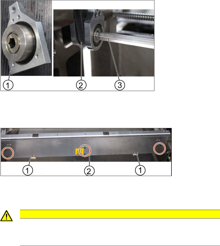
Key:
1) Screw (1 x)
2) Belt
3) Rod
Figure 3-35: Gear and conveyor rod
1. Remove the screw (1) to remove the rod (3). Use a spanner size 10 and a short Allen key size
4 to remove the screw.
2. Move the rod backwards.
Key:
1) Clamps
2) Screw (6 x)
Figure 3-36: Clamping plate
3. Remove the clamping plate off the conveyer system by unscrewing the screws (2) using an
Allen key size 2.0.
CAUTION
Springs inside the clamps
The clamps of the conveyer system bear springs.
Make sure all parts are retained.
ASM ProcessLens Single-lane 03/2020 Edition
38
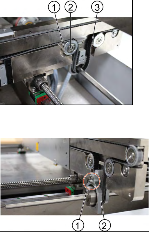
Key:
1) Tension ring
2) Screw
3) Belt
Figure 3-37: Tension ring of the conveyor unit
4. Loose the fastening ring of the belt to release the tension of the belt. Unscrew the screw (1) by
using an Allen key size 2.5.
Key:
1) Screw (3 x)
2) Gear
Figure 3-38: Gear
5. Remove the gear (2).
6. Change one screw using an Allen Key size 4.0 and 2 screws using an Allen key size 2.5.
7. Remove the belt and replace it with a new one.
8. Put back the gear by tighten the screws (3 x).
9. Put back the clamping plate by tighten the screws (6 x).
10. Put back the tension ring and fasten the belt by tighten the screw (1 x).