00900068-02_SM_ASM_ProcessLens_EN.pdf - 第38页
ASM Proces sLens Single - l ane 03/2020 Edit ion 38 Ke y: 1) Tens ion ring 2) Scre w 3) Belt Figure 3- 37 : Tension ring of the conveyor unit 4. Loose the f asten ing ring of the belt to rele ase the te nsion of the be l…
ASM ProcessLens Single-lane 03/2020 Edition
37
3.13 Changing the conveyor belt
Requirement:
● Machine is switched off.
● Tension meter.
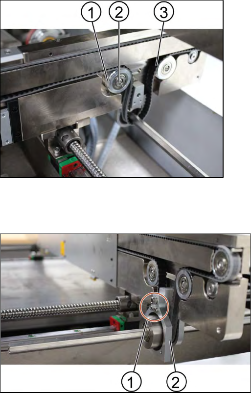
Key:
1) Screw (1 x)
2) Belt
3) Rod
Figure 3-35: Gear and conveyor rod
1. Remove the screw (1) to remove the rod (3). Use a spanner size 10 and a short Allen key size
4 to remove the screw.
2. Move the rod backwards.
Key:
1) Clamps
2) Screw (6 x)
Figure 3-36: Clamping plate
3. Remove the clamping plate off the conveyer system by unscrewing the screws (2) using an
Allen key size 2.0.
CAUTION
Springs inside the clamps
The clamps of the conveyer system bear springs.
Make sure all parts are retained.
ASM ProcessLens Single-lane 03/2020 Edition
38
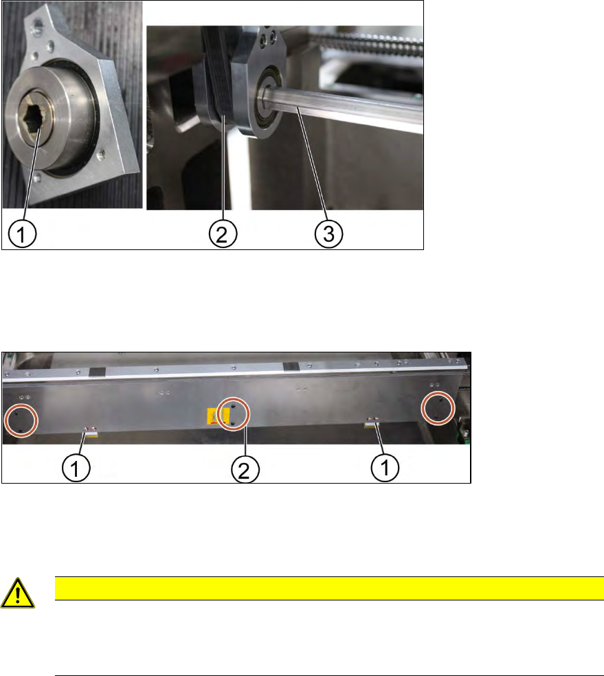
Key:
1) Tension ring
2) Screw
3) Belt
Figure 3-37: Tension ring of the conveyor unit
4. Loose the fastening ring of the belt to release the tension of the belt. Unscrew the screw (1) by
using an Allen key size 2.5.
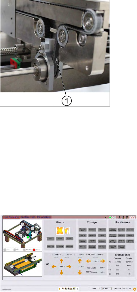
Key:
1) Screw (3 x)
2) Gear
Figure 3-38: Gear
5. Remove the gear (2).
6. Change one screw using an Allen Key size 4.0 and 2 screws using an Allen key size 2.5.
7. Remove the belt and replace it with a new one.
8. Put back the gear by tighten the screws (3 x).
9. Put back the clamping plate by tighten the screws (6 x).
10. Put back the tension ring and fasten the belt by tighten the screw (1 x).
ASM ProcessLens Single-lane 03/2020 Edition
39
Key:
1) Measurement point
Figure 3-39: Conveyor belt
11. Check the tension of the belt at the measurement point using a tension meter. The tension
should be 250 +/- 10 Hz.
12. The steps for the other conveyor system are the same.
Installation
Follow the removal instructions in reverse order for installation.
3.13.1 Check the function of the conveyor belt
Requirements:
● Machine is switched on.
● Inspection circuit board is placed at the beginning of the machine.
Figure 3-40: Diagnostic page
1. Go to the diagnostic page.
2. Click on the tab "Unit function".
3. Go to the section "Conveyor".
4. Click the button "PCB In" and the button "PCB Out".